Ultrasound information processing system and ultrasound information exchange protocol therefor

a technology of information processing system and ultrasound information, applied in the field of ultrasound information processing system, can solve the problems of not being able to easily upgrade the purchaser of an ultrasound processing system to a new ultrasound information processing algorithm, and being unable or impractical to substitute a first manufacturer's ultrasound component into a second manufacturer's ultrasound processing system,

Inactive Publication Date: 2005-01-04
U SYST
View PDF28 Cites 46 Cited by
  • Summary
  • Abstract
  • Description
  • Claims
  • Application Information

AI Technical Summary

Benefits of technology

According to a preferred embodiment, the UIEP compensates for the pipelined nature of serial bus communications by allowing proper inter-device synchronization as bulk image data is transferred and processed. An ultrasound source device, such as a scanner, generates image data in accordance with (a) intrinsic parameters that are included within each bulk data frame, together with (b) extrinsic parameters that are not included within each bulk data frame. However, for each bulk data frame, the host device requires knowledge of both the intrinsic and extrinsic parameters to properly process the frame. Accordin

Problems solved by technology

Accordingly, in the case of the prior art architectures supra, it is either impossible or impractical to substitute a first manufacturer's ultrasound component (such as a host, scanner, or digital signal processor) into a second manufacturer's ultrasound processing system.
As a result, it is less feasible for the purchaser of an

Method used


Image

  • Ultrasound information processing system and ultrasound information exchange protocol therefor
  • Ultrasound information processing system and ultrasound information exchange protocol therefor
  • Ultrasound information processing system and ultrasound information exchange protocol therefor

Examples


Embodiment Construction

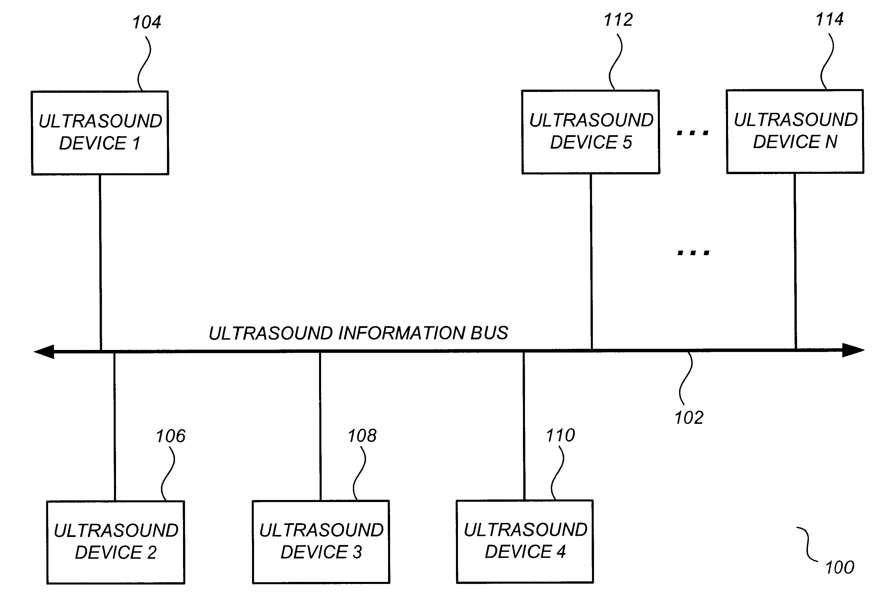
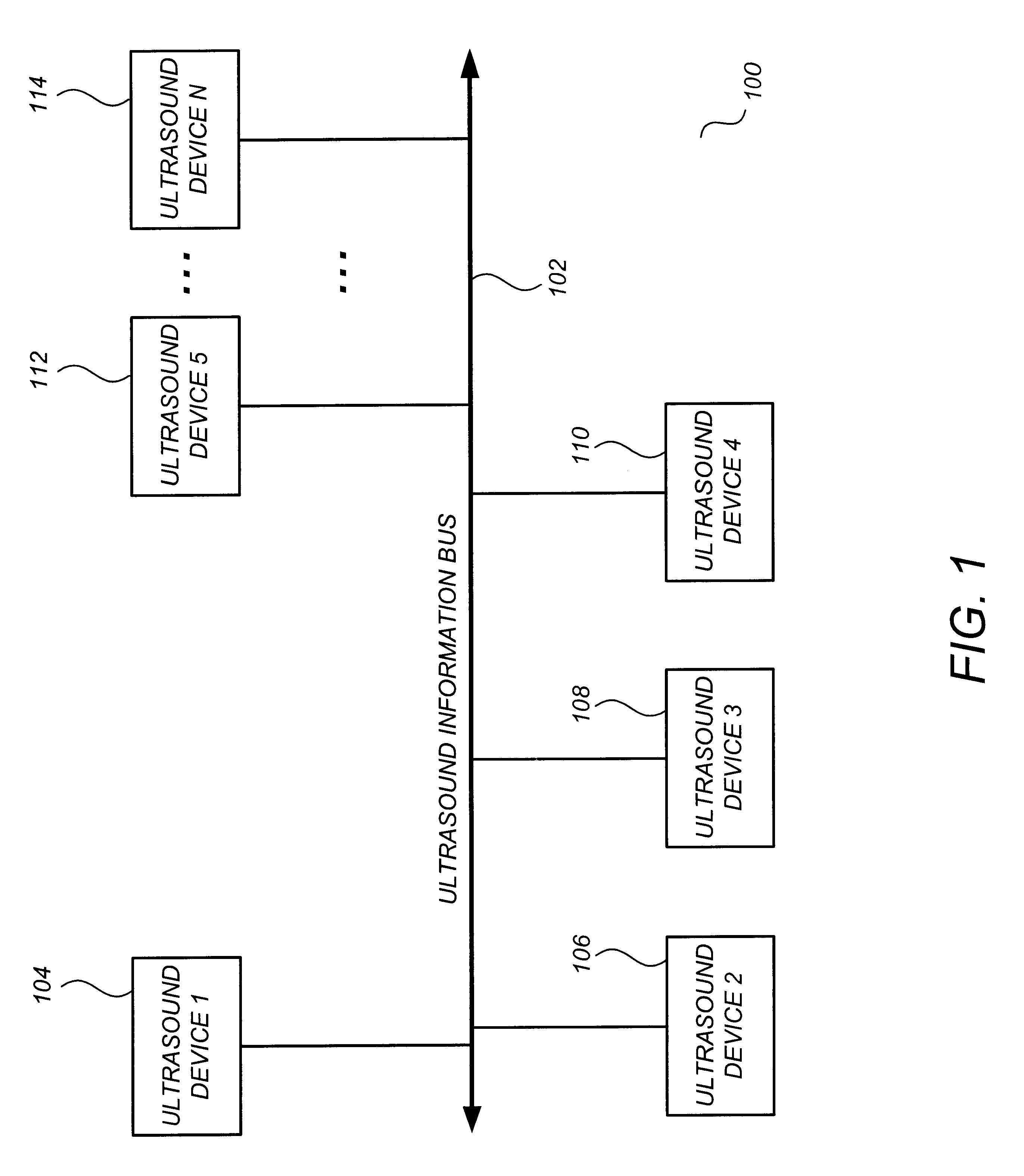
FIG. 1 shows an ultrasound information processing system 100 in accordance with a preferred embodiment. Ultrasound information processing system 100 comprises an ultrasound information bus 102 and a plurality of ultrasound devices 104-114 coupled thereto. The ultrasound information bus 102 is a high-speed serial bus operating in accordance with any of a variety of high-speed serial bus protocols, such as IEEE 1394 / 1995 (“Firewire”), USB, Fibre Channel, or others. In general, the high-speed serial bus protocol may be any protocol that provides for both isochronous and asynchronous data transfer, as described in Ser. No. 09 / 224,635, supra.

The ultrasound devices 104-114 shown in FIG. 1 may be any of a variety of device combinations for achieving a desired ultrasound information processing functionality. For example, ultrasound device 104 may be a host computer for providing overall system control, user display, user input, and image processing functions. Ultrasound device 106 may be a ...


PUM


Abstract

An ultrasound information processing system comprises a plurality of ultrasound devices coupled to a high-speed serial ultrasound information bus, wherein each ultrasound device comprises a program for communicating with other ultrasound devices according to an ultrasound information exchange protocol (UIEP). The UIEP is a lightweight, connection-oriented protocol adapted to efficiently transfer ultrasound information among different devices on the ultrasound information bus. Each ultrasound device comprises an application layer program for performing an ultrasound function, as well as a lower protocol layer program for receiving and sending data across the ultrasound information bus according to a high-speed serial bus standard that provides both isochronous and asynchronous data delivery. The ultrasound information exchange protocol (UIEP) program is adapted to receive a communication request from the application layer, open a connection-oriented communication session with the requested ultrasound device, and transfer ultrasound information through the lower protocol layer and across the ultrasound information bus to the requested device. Advantageously, any ultrasound device manufacturer provided with the UIEP program may readily generate application layer code capable of communicating with other manufacturers' ultrasound devices across the ultrasound information bus, without requiring specific knowledge of the internal structure of the other manufacturers' devices or of the specific frame/packet structure of the UIEP/lower layer protocols themselves.

Description

FIELDThis patent specification relates to the field of ultrasound information processing systems. In particular, the present invention relates to an architecture for a flexible, high-performance, reduced cost, and upgradable ultrasound information processing system and a standardized protocol for allowing ready interoperability of ultrasound devices within and across such systems.BACKGROUNDUltrasound imaging systems are advantageous for use in medical diagnosis as they are non-invasive, easy-to-use, and do not subject patients to the dangers of electromagnetic radiation. An ultrasound imaging system transmits sound waves of very high frequency (e.g., 2 MHz to 10 MHz) into the patient and processes echoes reflected from structures in the patient's body to form two dimensional or three dimensional images. Many ultrasound information processing algorithms are known in the art, for example, echo mode (“B mode”) processing algorithms, motion mode (“M mode”) processing algorithms, Doppler...

Claims


Application Information

Patent Timeline
IPC IPC(8): A61B5/0456A61B5/0452A61B7/00A61B7/04A61B8/06G01S15/89G01S15/00G01S7/52A61B5/352A61B8/00G16H30/20G16H40/67
CPCA61B5/0456A61B7/04A61B8/00A61B8/06A61B8/13G06F19/321G01S7/52025G01S7/52034G01S15/899A61B2560/0271A61B8/4411G16H30/20G16H40/67A61B5/352
Inventor YU, ZENGPINLIN, SHENGTZYE, EDDYNEFF, THOMAS P.
Owner U SYST
Why Eureka
Try Eureka