Method and apparatus for injection molding light metal alloy
a technology of light metal alloy and injection molding, which is applied in the direction of metal founding, chemical apparatus and processes, etc., can solve the problems of large size of the apparatus, excessive height of the entire apparatus, and defective products, so as to improve the quality of the products, improve the resistance to passage, and ensure the effect of molding operation
- Summary
- Abstract
- Description
- Claims
- Application Information
AI Technical Summary
Benefits of technology
Problems solved by technology
Method used
Image
Examples
first embodiment
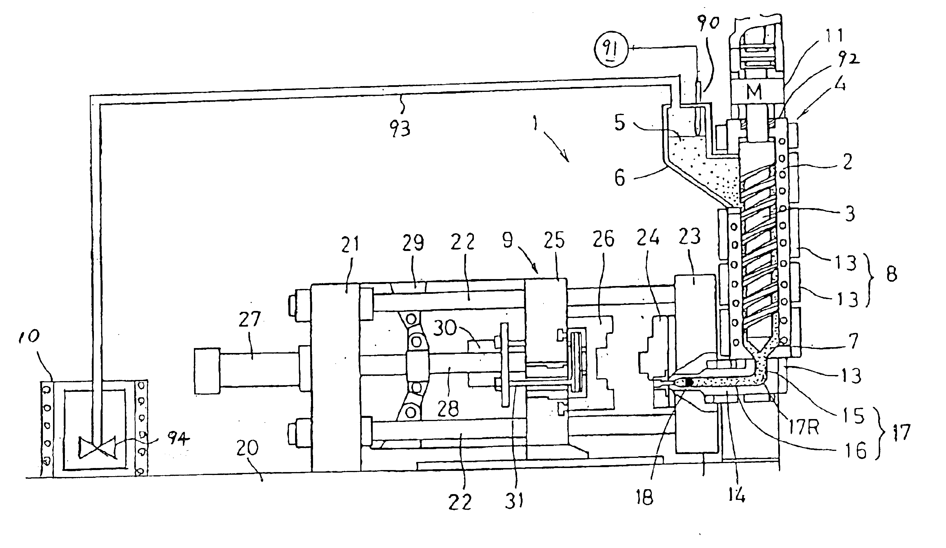
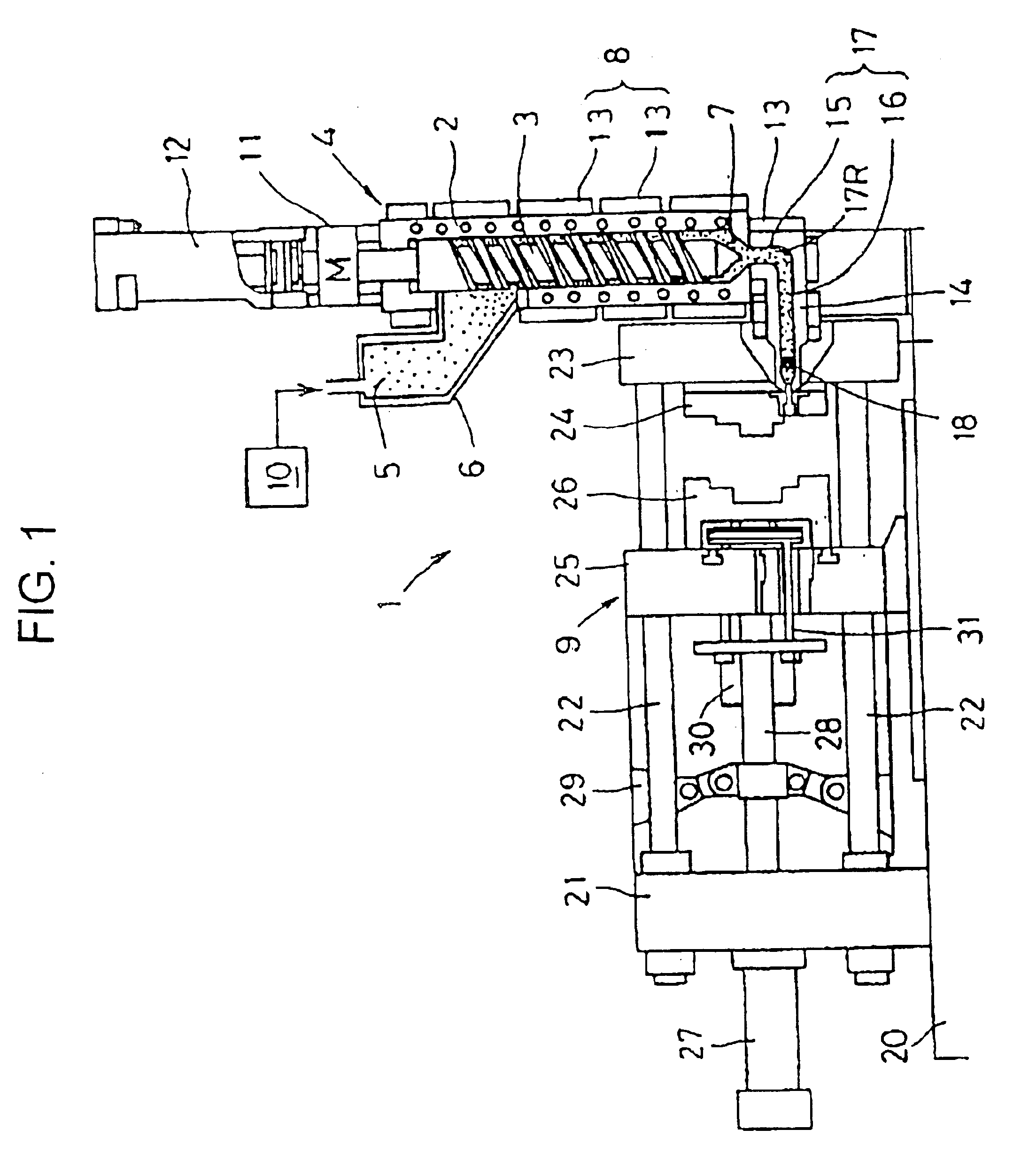
FIG. 1 shows the present invention.
An injection molding apparatus 1 for light metal alloys according to this embodiment comprises a screw extruder 4 disposed vertically and having an extrusion screw 3 disposed rotatably at the inside of a chamber 2 and a hopper 6 connected to the upper end of the chamber 2 for storing molten metal 5.
Further, the apparatus 1 comprises a temperature control unit 8 used for temperature control, for example, cooling such that the molten metal 5 supplied from the hopper 6 into the chamber 2 is formed into semi-solidified slurry 7 and a clamping device 9 into which the semi-solidified slurry 7 discharged from a discharge port at a lower end of the chamber 2 is injected.
Among the constituent components of the apparatus 1, the hopper 6 is adapted to receive the molten metal 5 melted in a melting furnace 10 and store the same in a molten state, and a lower end opening of the hopper 6 is connected to an upper end of the chamber 2.
Further, a sealing unit (not ...
second embodiment
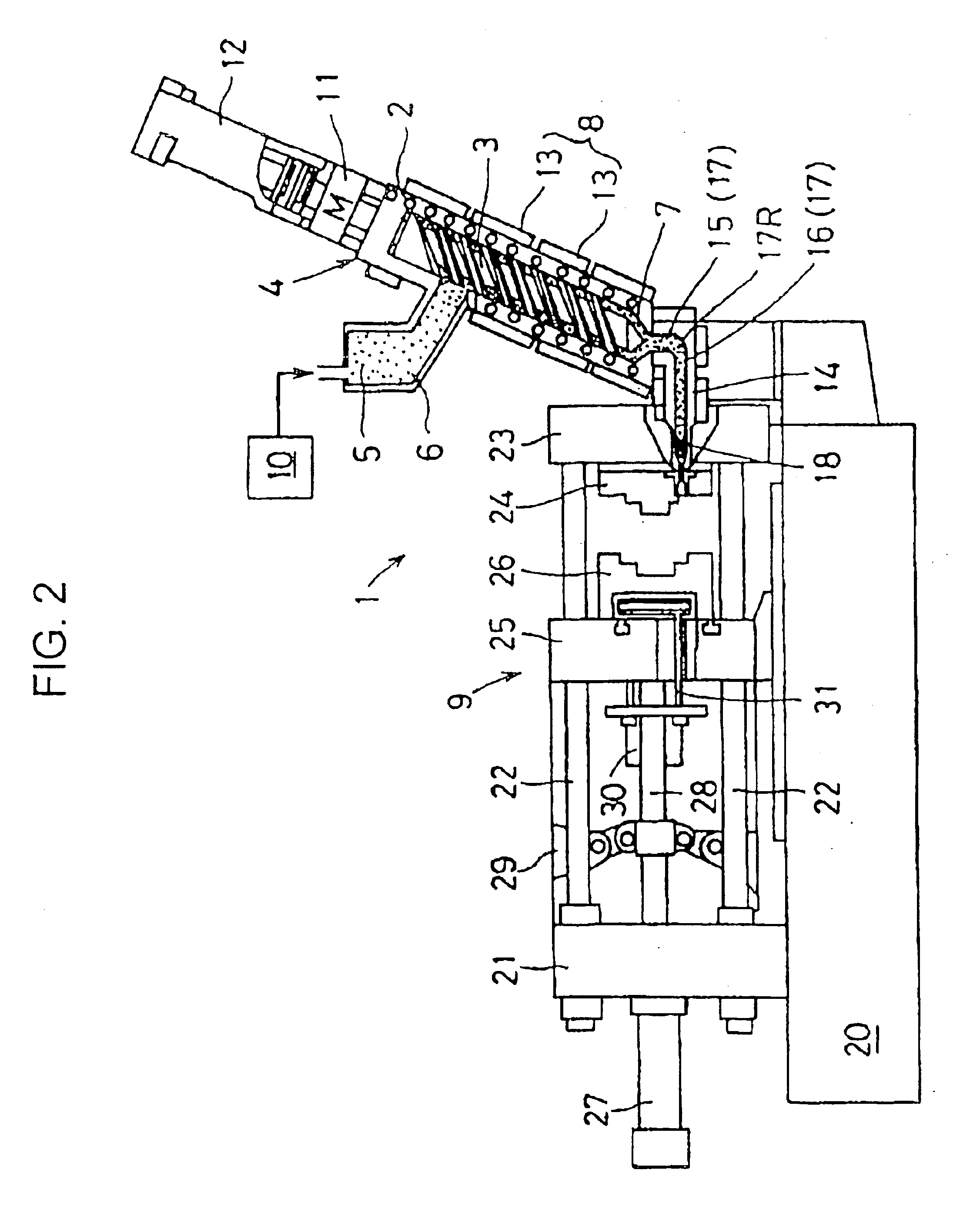
FIG. 2 shows the present invention.
In this embodiment, a chamber 2 for a screw extruder 4 is inclined in a state somewhat turned down to the side opposite to the clamping device 9, by which the height for the entire apparatus can be suppressed further lower compared with the case of the first embodiment.
The degree of inclination of the screw extruder 4 is set substantially equal with the helical angle of the extrusion screw 3 and, at such degree of inclination satisfactory stable operation can be conducted without removing the pores at the inside of the chamber 2 or without deposition of the semi-solidified slurry 7 to the upper portion of the shaft.
In the present invention, “substantially vertical” means not only that the chamber 2 is disposed vertically but also that it is inclined to such an extent as removal of bubbles can be saved at the inside of the chamber 2 or deposition does not occur to the upper portion of the shaft.
Since other constitutions and functions are identical w...
third embodiment
FIG. 3 shows the present invention.
In this embodiment, an extrusion screw 3 is inserted in a chamber 2 so as not to move in the axial, namely, vertical direction, so that the injection cylinder 12 is not disposed to the upper end of a driving motor 11.
Instead, a discharge port at the lower end of a chamber 2 is connected with an upper portion at the front end of a metering cylinder (connection member) 34, in which an injection plunger 33 protruding and retracting horizontally is inserted therein. An injection flow channel 17 comprising a vertical first channel 15 and a horizontal second channel 16 is constituted at the front end of the metering cylinder 34, and a check valve (not illustrated) for preventing the semi-solidified slurry 7 in the second channel 16 from flowing backwardly to the chamber 2 is disposed in the first channel 16.
Further, an injection cylinder 36 is disposed to the rear end of the metering cylinder 34 for protruding an injection plunger 33 toward a stationary ...
PUM
 Abstract
Description
Claims
Application Information
 - R&D
- Intellectual Property
- Life Sciences
- Materials
- Tech Scout
- Unparalleled Data Quality
- Higher Quality Content
- 60% Fewer Hallucinations
Browse by: Latest US Patents, China's latest patents, Technical Efficacy Thesaurus, Application Domain, Technology Topic, Popular Technical Reports.
© 2025 PatSnap. All rights reserved.Legal|Privacy policy|Modern Slavery Act Transparency Statement|Sitemap|About US| Contact US: help@patsnap.com


