Parallel hybrid vehicle

a hybrid vehicle and parallel technology, applied in the direction of electric control, gearing, machines/engines, etc., can solve the problem of torsional vibration in the drive system that is easy to be developed

Inactive Publication Date: 2005-01-11
JATCO LTD
View PDF12 Cites 60 Cited by
  • Summary
  • Abstract
  • Description
  • Claims
  • Application Information

AI Technical Summary

Benefits of technology

Since, in the above-described parallel hybrid vehicle, a torque augmentation function by means of a gear ratio (sun gear/ring gear) of the planetary gear mechanism constituting the torque synthesis mechanism is provided, it is not necessary to interpose a torque converter between the engine and the transmission. However, if a fluid coupling such as a torque converter as described above is not provided in the drive system of the hybrid vehicle, a torsional vibration in the drive system would easily be developed. This may be caus

Problems solved by technology

However, if a fluid coupling such as a torque converter as described above is not provided in the dri

Method used


Image

  • Parallel hybrid vehicle
  • Parallel hybrid vehicle
  • Parallel hybrid vehicle

Examples


first embodiment

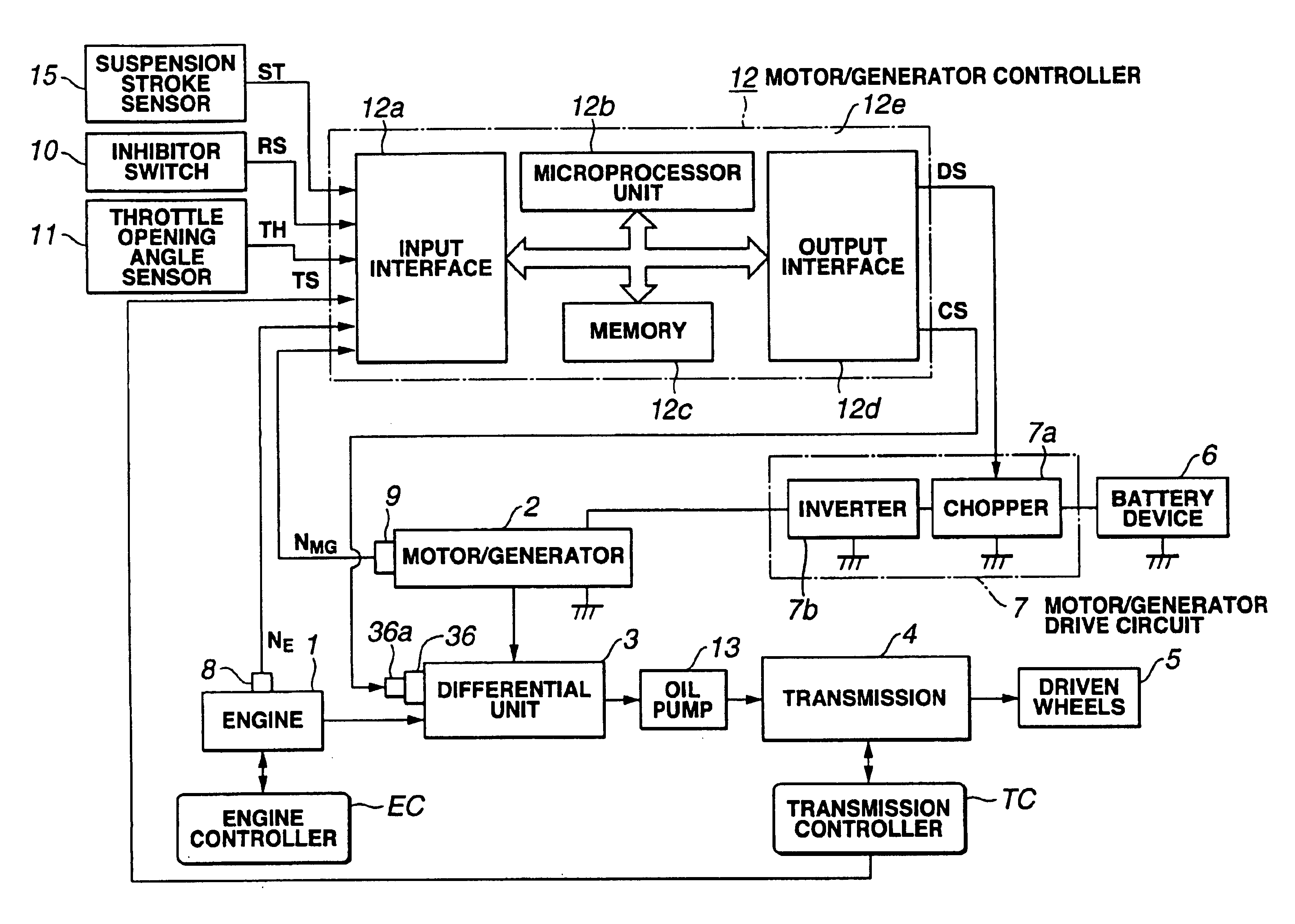
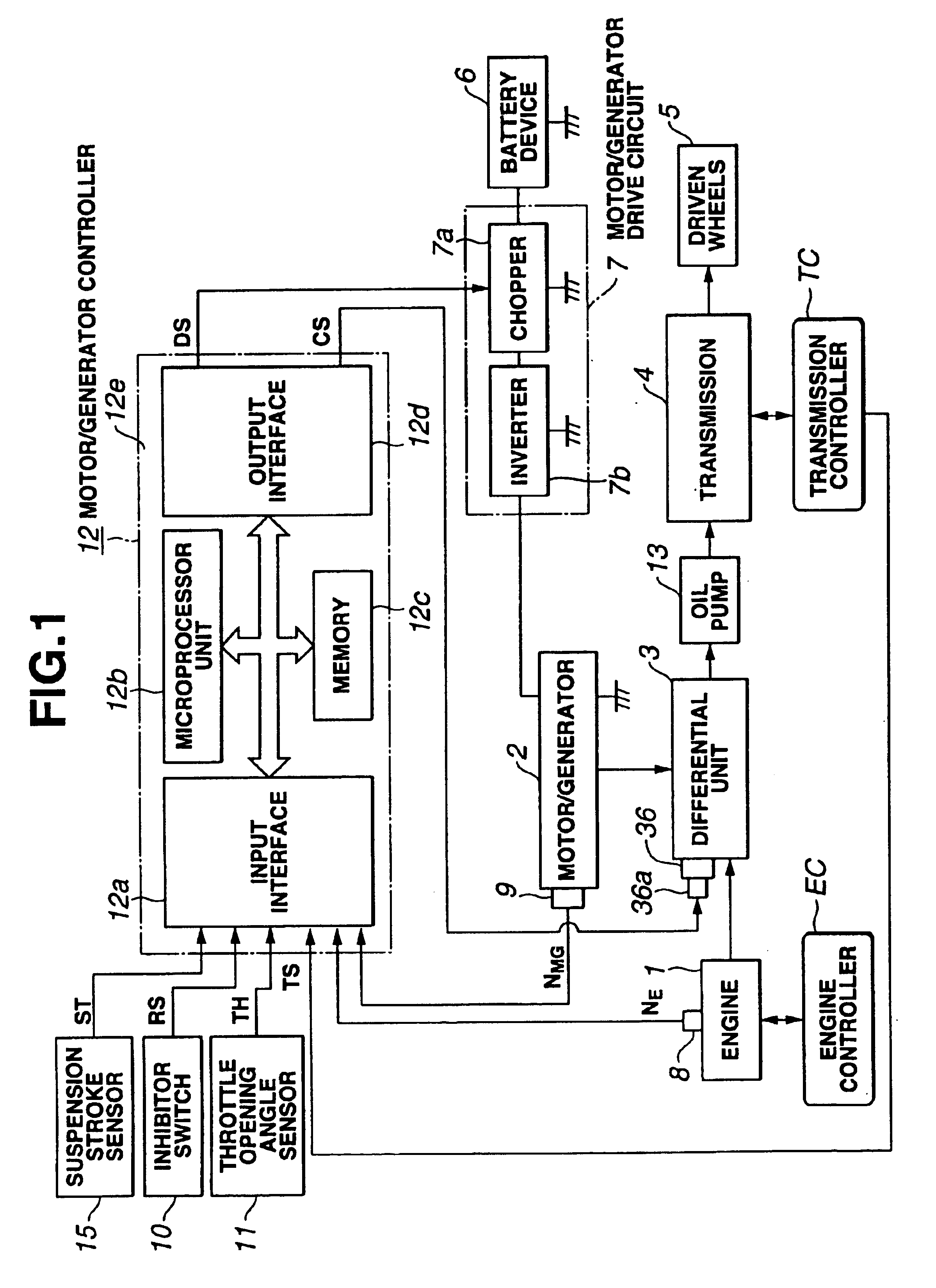
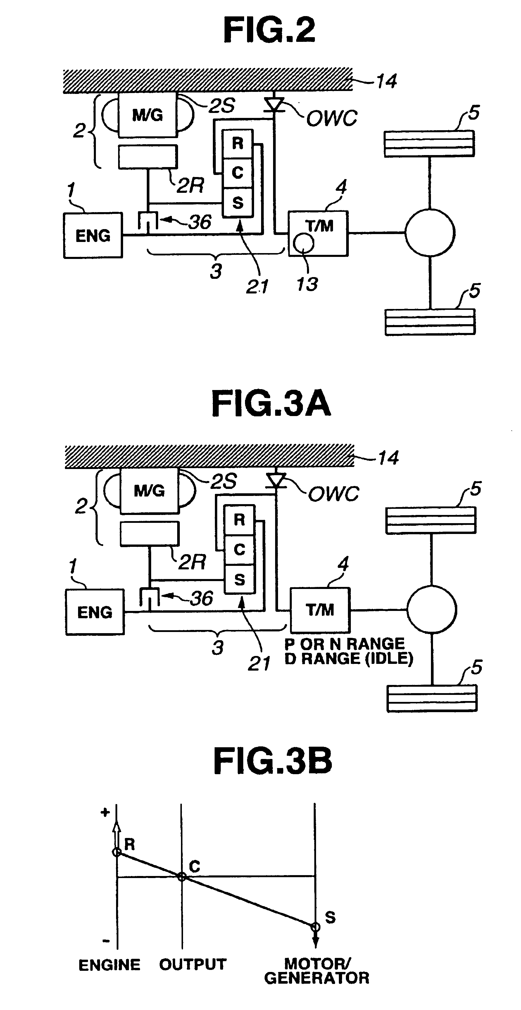
In addition, a lock-up clutch 36 to control linkage states of both of motor / generator 2 and engine 1 is interposed between rotor 2R of motor / generator 2 and the output end of engine 1. A one-way clutch OWC is interposed between pinion carrier C of planetary gear mechanism 21, viz., an input end of transmission 4 and a casing 14. One-way clutch OWC restricts a rotational direction of each of pinion carrier C and transmission 4 only in the positive rotational rotation and engages in the case of the reverse rotational direction to disable the reverse rotation. It is noted that although a damper may be interposed between engine 1 and ring gear R of planetary gear mechanism 21, in the first embodiment, the presence of the damper can be neglected since a resonance frequency of the damper is high.

Lock-up clutch 36, for example, is constituted by a wet type multiple-plate clutch. When a control signal CS supplied to an electromagnetic solenoid 36a of an electromagnetic valve (not shown) to ...

second embodiment

As described above, specific angular vibration frequency ωn of the drive system and damping factor ξ thereof are learned and corrected to their appropriate values so that the detected vibration state becomes a predetermined vibration state when motor / generator torque T*M / G1 and third motor / generator torque T*M / G3 are calculated and set. The torsional vibration of the drive shaft can accurately be prevented from occurring. It is noted that, in the second embodiment, the torsional vibration is detected according to the detection of the acceleration acted upon the vehicular body. However, the torsional vibration of the drive shaft may be detected from a difference between revolution speeds of an output axle of the transmission 4 and driven wheels 5.

In addition, in each of the preferred embodiments, the microcomputers are used for the respective controllers. However, various kinds of arithmetic process circuits may be used for the respective controllers. It is noted that the position of...


PUM


Abstract

In a parallel hybrid vehicle, a controlling section controls an engine and a motor/generator, a torque from the engine and the motor/generator being transmitted to driven wheels via a transmission and a drive shaft. The controlling section comprises: an engine torque calculating section that calculates an engine torque and a torsional vibration suppression torque calculating section that calculates a torsional vibration suppression torque to suppress a torsional vibration developed on the drive shaft according to the engine torque calculated by the engine torque calculating section, the torsional vibration suppression torque calculated by the torsional vibration suppression torque calculating section being outputted from the motor/generator.

Description

BACKGROUND OF THE INVENTION1. Field of the InventionThe present invention relates to a parallel hybrid (electric) vehicle having an engine and a motor / generator (a motor serving also as a generator), an output torque of either one or both of these engine and motor / generator being transmitted to a transmission via a torque synthesis mechanism so that a vehicular running driving force is obtained from either one or both of the engine and motor / generator.2. Description of the Related ArtA U.S. Pat. No. 6,054,776 issued on Apr. 25, 2000 (which corresponds to a Japanese Patent Application First Publication No. Heisei 10-304513 published on Nov. 12, 1998) exemplifies a previously proposed parallel hybrid vehicle, In the disclosed parallel hybrid vehicle, the torque synthesis mechanism constituted by a differential gear mechanism (planetary gear mechanism) is used to synthesize output torques of the engine and the motor / generator and the synthesized output torque thereat is transmitted via...

Claims


Application Information

Patent Timeline
IPC IPC(8): B60K6/04B60K6/00B60K6/20B60K17/04B60K6/48B60K6/54B60K6/547B60L50/16B60W10/02B60W10/06B60W10/08B60W20/00F02D17/00F02D29/00F02D29/02F02D29/06F02D41/04F02D45/00F16H37/08
CPCB60K6/365B60K6/383B60K6/387B60K6/48B60K6/54B60W10/02B60W10/08B60W2710/083Y02T10/642Y02T10/6221B60L2240/423B60L2240/441B60W20/00B60W2510/0638B60W2510/0695B60W2510/1095B60W2530/10B60W2710/0644Y10S903/946Y10S903/91Y10S903/917Y10S903/913Y10S903/919F16H3/724Y02T10/62Y02T10/64B60W2050/0042B60W30/18027B60W2710/0666B60W10/04
Inventor FUJIKAWA, MASATO
Owner JATCO LTD
Why Eureka
Try Eureka