Radiation patterning tools, and methods of forming radiation patterning tools

Inactive Publication Date: 2005-01-11
MICRON TECH INC
View PDF4 Cites 14 Cited by
  • Summary
  • Abstract
  • Description
  • Claims
  • Application Information

AI Technical Summary

Benefits of technology

In particular aspects, the invention includes a radiation patterning tool which can be utilized to form relatively circular contacts in situations in which an array of contacts has a different pitch along a row of the array than along a column of the array. An alternating phase shift can give a well-defined contact in the small pitch (dense) direction. Rim shifters are added in the larger pitch direction to force the circular form of the contact openings. In further aspects of the invention, side-lobe-suppressing patterns can be formed between adjacent rims. Among the advantages of the inven

Problems solved by technology

Difficulties exist in fabricating reticles which can pattern circles having diameters on the order of microns and sub-microns.
Typically, ovals are patterned instead of the desired circles, which can cause more semiconductor real estate to be consumed than would be utilized if c

Method used


Image

  • Radiation patterning tools, and methods of forming radiation patterning tools
  • Radiation patterning tools, and methods of forming radiation patterning tools
  • Radiation patterning tools, and methods of forming radiation patterning tools

Examples


first embodiment

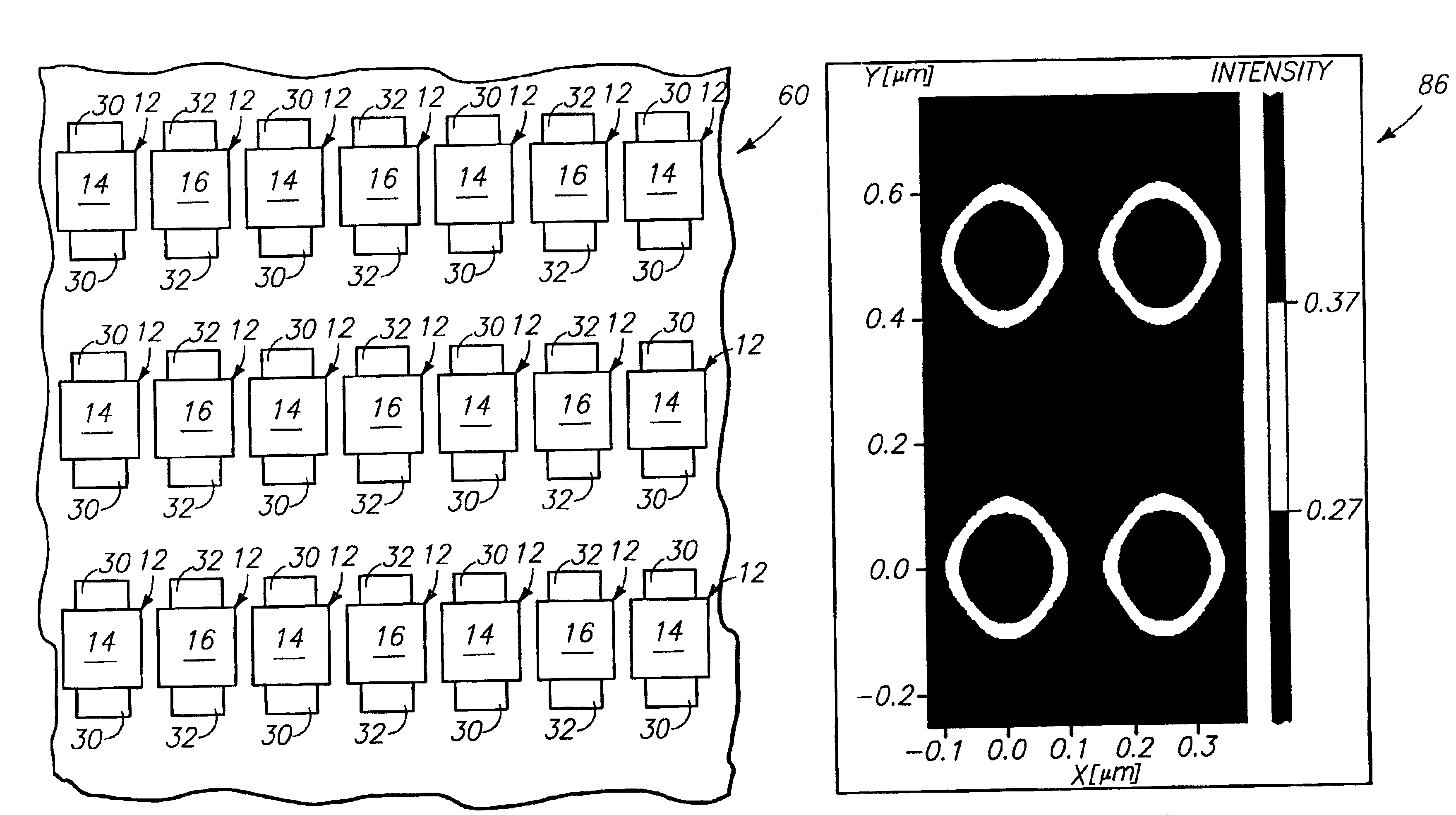
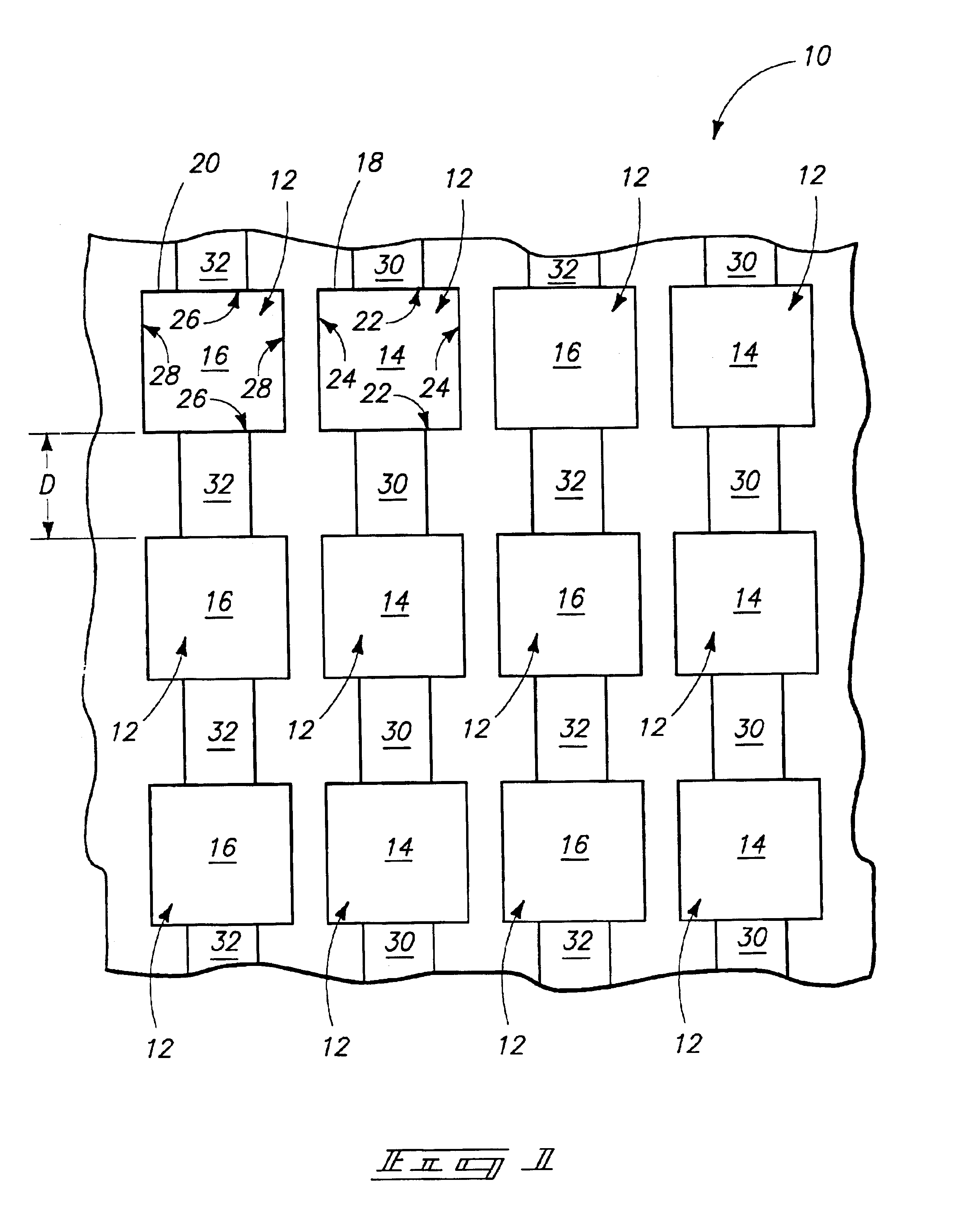
Referring initially to FIG. 1, a first embodiment radiation patterning tool construction 10 comprises an array of feature patterns 12 arranged in vertically-extending columns and horizontally-extending rows. The feature patterns 12 are divided between a pair of defined types. Specifically, some of the feature patterns 12 are a first type 14 (also referred to herein as first feature patterns) and others are a second type 16 (also referred to herein as second feature patterns). The first type of feature pattern rotates a phase of a wavelength of light to a first orientation as the wavelength passes through it; and the second type of feature pattern rotates the phase of the wavelength of light to a second orientation as the wavelength passes through it. The second orientation can be from about 170° to about 190° relative to the first orientation, can be about 180° relative to the first orientation, and can be exactly 180° relative to the first orientation. The light passing through fea...

second embodiment

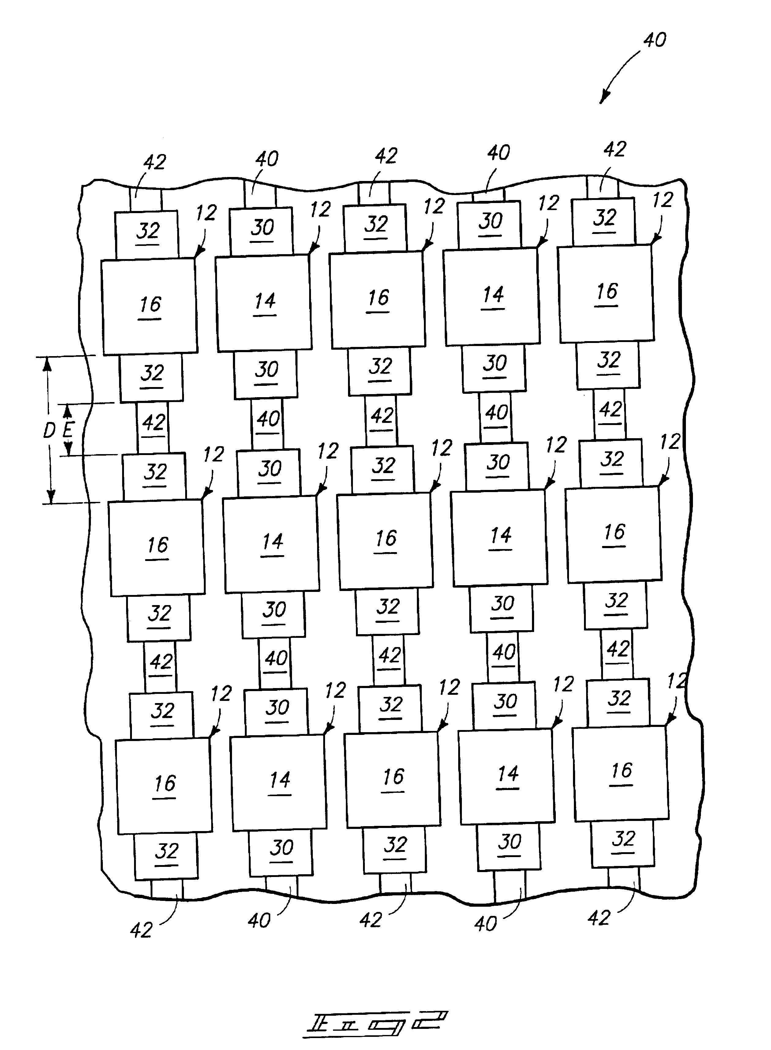
Referring to FIG. 2, a second embodiment radiation patterning tool 40 is illustrated. Similar numbering is utilized for describing the tool 40 as is utilized above in describing the tool 10 of FIG. 1, where appropriate. Accordingly, tool 40 comprises first feature patterns 14, second feature patterns 16, first rims 30 and second rims 32. Also, the feature patterns are arranged in an array having columns and rows, and there is a distance “D” between adjacent feature patterns along the columns of the array. The distance “D” of the tool 40 can be the same or different than the distance “D” of the tool 10 of FIG. 1, and in typical embodiments the distance “D” of tool 40 will be larger than that of tool 10. In either tool 10 of FIG. 1 or tool 40 of FIG. 2, distance “D” can be about the size of feature pattern which is ultimately to be formed with the tool.

The rims 30 and 32 do not extend an entirety of the distance between adjacent feature patterns along columns of the array, but rather ...


PUM


Abstract

The invention includes, for example, a radiation patterning tool which can be utilized to form relatively circular contacts in situations in which an array of contacts has a different pitch along a row of the array than along a column of the array. An alternating phase shift can give a well-defined contact in the small pitch (dense) direction. Rim shifters are added in the larger pitch direction to force the circular form of the contact openings. In further aspects of the invention, side-lobe-suppressing patterns can be added between adjacent rims. The invention also includes methods of forming radiation patterning tools.

Description

TECHNICAL FIELDThe invention pertains to radiation patterning tools, and to methods of forming radiation patterning tools. In particular aspects, the invention pertains to radiation patterning tools in which a rim is formed proximate a feature pattern. The rim is configured to impart a rotation in phase to light passing through the rim which is about 180 degrees from a rotation in phase imparted to the wavelength of light as it passes through the feature pattern.BACKGROUND OF THE INVENTIONPhotolithography is commonly used during formation of integrated circuits on semiconductor wafers. More specifically, a form of radiant energy (such as, for example, ultraviolet light) is passed through a radiation patterning tool and onto a semiconductor wafer. The radiation patterning tool can be, for example, a photomask or a reticle, with the term “photomask” traditionally being understood to refer to masks which define a pattern for an entirety of a wafer, and the term “reticle” traditionally ...

Claims


Application Information

Patent Timeline
IPC IPC(8): G03F1/00G03F1/26
CPCG03F1/30G03F1/36G03F1/29G03F1/00G03F1/26
Inventor DULMAN, H. DANIEL
Owner MICRON TECH INC
Why Eureka
Try Eureka