Radio-frequency antenna for a magnetic resonance system

a radio-frequency antenna and magnetic resonance technology, applied in the field of radio-frequency antennas for magnetic resonance systems, can solve the problem that mode separation cannot be achieved through frequency-dependent impedances, and achieve the effect of high excitation efficiency

Inactive Publication Date: 2005-01-11
SIEMENS HEALTHCARE GMBH
View PDF13 Cites 26 Cited by
  • Summary
  • Abstract
  • Description
  • Claims
  • Application Information

AI Technical Summary

Benefits of technology

In an embodiment wherein the spacing of the conductor from the end ring or the spacings of the conductors from one another or from the end ring, assumes or assume a maximum value and a minimum value and the difference between maximum value and minimum value amounts to at least 30%, preferably 50 through 90%, of the offset of the end rings relative to one another, then an especially high excitation efficiency is achieved.

Problems solved by technology

Due to this tuning to the same resonant frequency (namely, the Larmor frequency), mode separation is no longer possible by means of frequency-dependent impedances, neither in the transmission mode nor in the reception mode.

Method used


Image

  • Radio-frequency antenna for a magnetic resonance system
  • Radio-frequency antenna for a magnetic resonance system
  • Radio-frequency antenna for a magnetic resonance system

Examples


Embodiment Construction

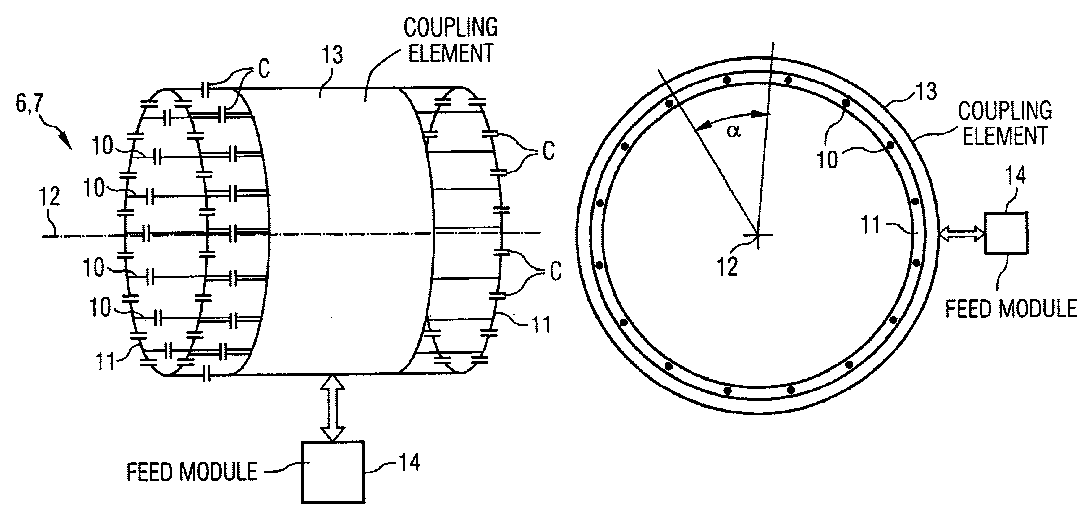
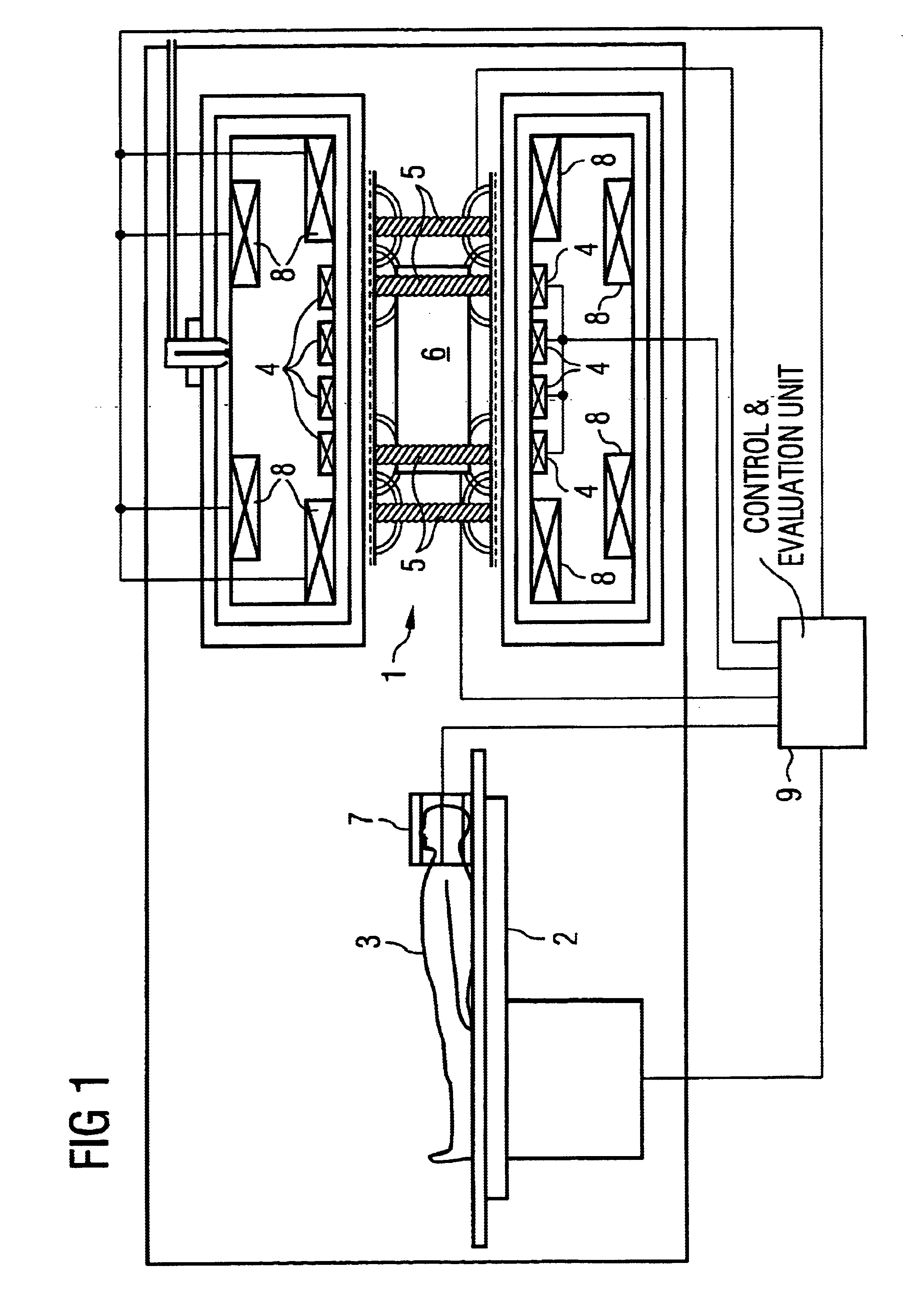
The magnetic resonance system shown in FIG. 1 has an examination space 1. A patient 3 (in general: an examination subject 3) can be introduced into the examination space 1 with a patient bed 2. The examination space 1 is essentially cylindrical.

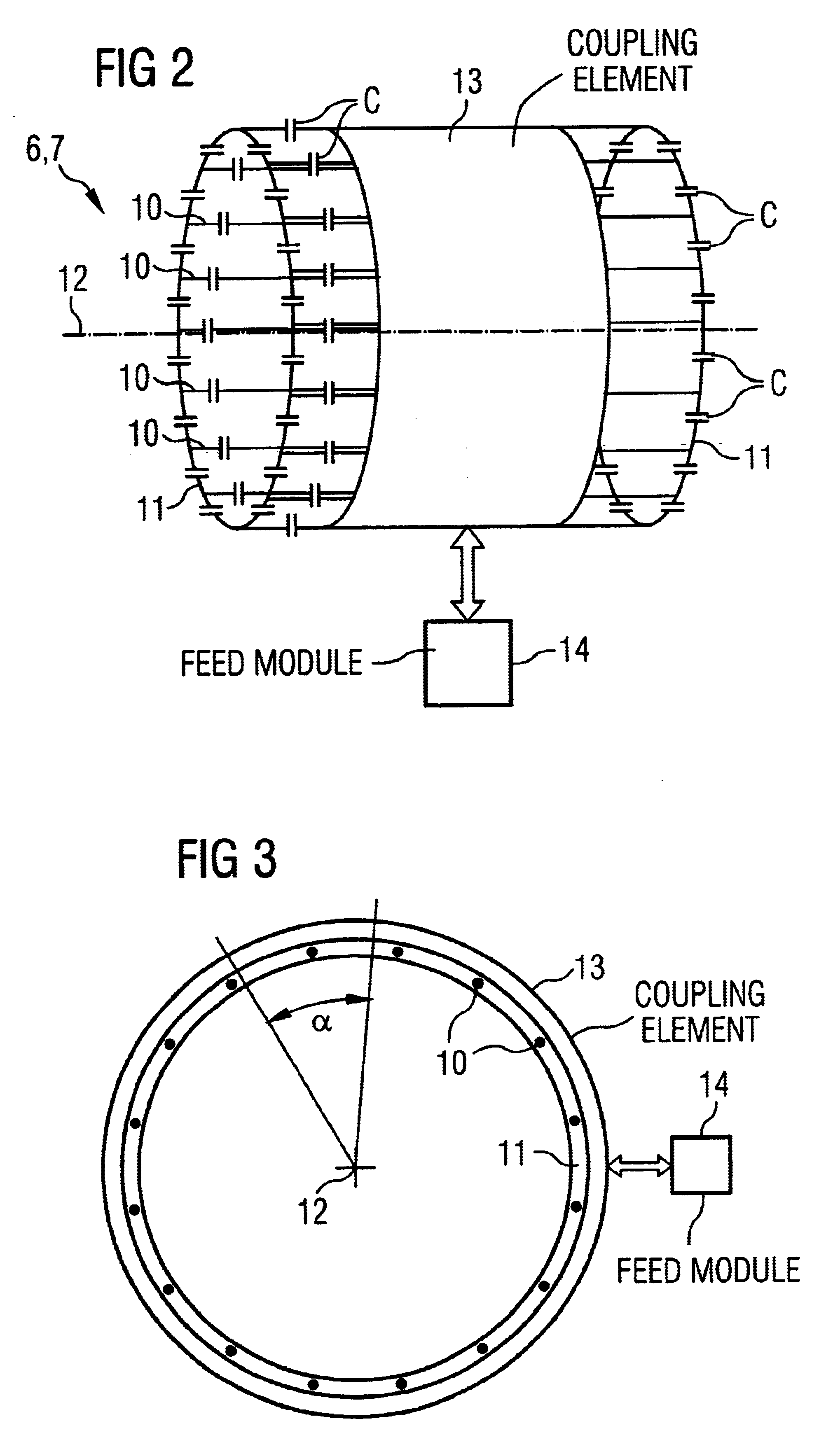
The examination space 1 is surrounded by various magnets and magnet systems. First, there is a basic magnet 4. The basic magnet 4 generates a homogeneous basic magnetic field. A gradient magnet system 5 is also present. Gradient fields, which are required for generating meaningfully interpretable magnetic resonance signals, are generated with the gradient magnet system 5. The magnet system also has a whole-body coil 6. The whole-body coil 6 is fashioned as a radio-frequency antenna 6. Given operation as transmission antenna, it serves for exciting magnetic resonance signals in the examination subject 3. Given operation as reception antenna, it serves for the reception of previously excited magnetic resonance signals of the examination subject...


PUM


Abstract

A radio-frequency antenna has two end rings and a number of antenna rods that form a birdcage resonator. A coupling element couples high-frequency electromagnetic energy into the resonator in the transmission mode and out therefrom in the reception mode. The coupling element is fashioned as a conductor system tangentially surrounding the resonator and into which a high-frequency systems of currents can be fed in the transmission mode or from which a high-frequency system of currents can be fed out in the reception case. The coupling element is coupled only inductively to the resonator.

Description

BACKGROUND OF THE INVENTION1. Field of the InventionThe present invention is directed to a radio-frequency antenna for a magnetic resonance system, of the type having two end rings and a number of antenna rods, wherein the end rings are arranged concentrically around an antenna axis and are axially offset relative to one another and the antenna rods connect the end rings to one another, and wherein a coupling element can couple radio-frequency electromagnetic energy into the end rings and into the antenna rods in the transmission mode and can couple radio-frequency electromagnetic energy out therefrom in the reception mode.2. Description of the Prior ArtRadio-frequency antennas of this type are known as birdcage resonators. As a rule, the antenna rods therein are arranged parallel to the antenna axis.Birdcage resonators have a number of oscillatory modes, each of which can have its own resonant frequency. It is generally advantageous in magnetic resonance applications to tune the in...

Claims


Application Information

Patent Timeline
Patent Type & Authority Patents(United States)
IPC IPC(8): G01R33/34A61B5/055
CPCG01R33/34046
Inventor HEID, OLIVERVESTER, MARKUS
Owner SIEMENS HEALTHCARE GMBH
Why Eureka
Try Eureka