Liquid crystal display device having switchable reflective layer
- Summary
- Abstract
- Description
- Claims
- Application Information
AI Technical Summary
Benefits of technology
Problems solved by technology
Method used
Image
Examples
first embodiment
(First Embodiment)
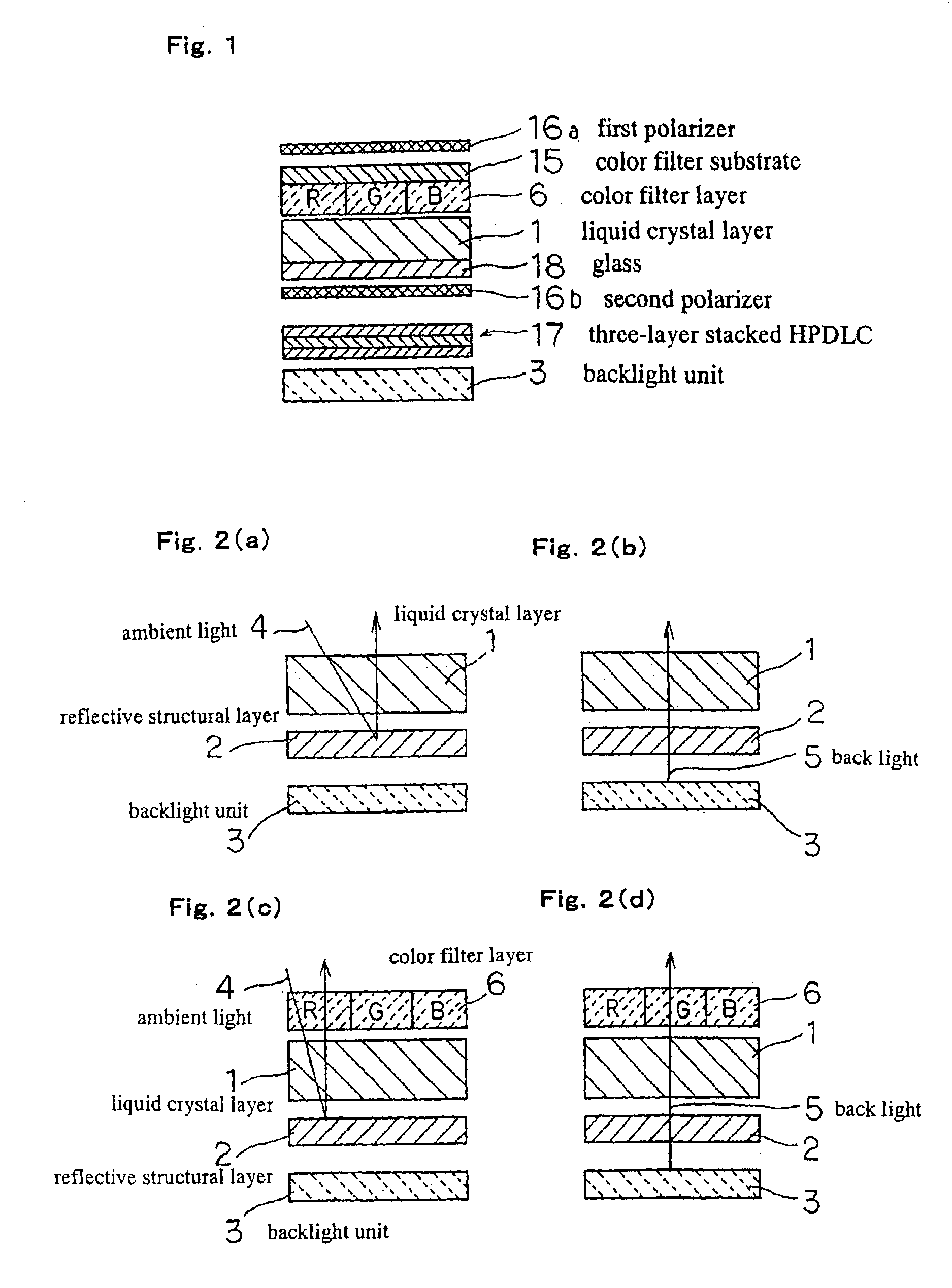
We first refer to FIG. 1, in which is shown a side sectional view of the details of the construction of an example of the liquid crystal display device of the present embodiment.
The liquid crystal display device is of a construction that includes: first polarizer 16a that formed on the top layer; below first polarizer 16a, color filter layer 6 that is composed of filters that each transmit only R (red), G (green), or B (blue) and in which color filter substrate 15 is formed as the upper layer side; below color filter layer 6, liquid crystal layer 1 that is formed on glass 18 for projecting image information; second polarizer 16b that is below liquid crystal layer 1, i.e., below glass 18; three-layer HPDLC 17 having reflectors in which reflectance can be electrically switched that is arranged below second polarizer 16b, i.e., that is below liquid crystal layer 1; and then, on the lowest layer, backlight unit 3, which is the lighting for irradiating light from the ba...
second embodiment
(Second Embodiment)
We next refer to FIG. 8, in which is shown a side sectional view showing the details of the construction of an example of a liquid crystal display device of the present embodiment.
As shown in FIG. 8(a), liquid crystal display device of this embodiment is a construction including, in order from the uppermost layer: first polarizer 116a, color filter substrate 115, color filter layer 106, liquid crystal layer 101, thin-film glass 127, three-layer stacked HPDLC 117, second polarizer 116b, and, at the lowermost layer, backlight unit 103.
The liquid crystal display device of the present embodiment therefore differs from the liquid crystal display device of the first embodiment in that thin-film glass 127 and three-layer stacked HPDLC. 117 are stacked together between liquid crystal layer 101 and second polarizer 116.
Further, in the liquid crystal display device of the present embodiment, only first polarizer 116a contributes to display during reflective display. This di...
third embodiment
(Third Embodiment)
FIG. 9 shows a side sectional view of the details of the construction of an example of the liquid crystal display device of the present embodiment, and FIG. 10 shows the basic construction of the liquid crystal display device of the present embodiment.
As shown in FIG. 9(a), the liquid crystal display device of the present embodiment is a construction that includes, in order from the uppermost layer: first polarizer 216a, color filter substrate 215, first color filter layer 206a, liquid crystal layer 201, glass 218, three-layer stacked HPDLC 217, second polarizer 216b, second color filter layer 206b, and, at the lowermost layer, backlight unit 203. As with first color filter layer 206a, which is formed on color filter substrate 215, second color filter layer 206b is formed on a color filter substrate, but for the sake of simplification, the color filter substrate of second color filter layer 206b is not shown in FIG. 9.
As shown in FIG. 10, the liquid crystal display...
PUM
| Property | Measurement | Unit |
|---|---|---|
| Phase | aaaaa | aaaaa |
| Reflection | aaaaa | aaaaa |
| Optical reflectivity | aaaaa | aaaaa |
Abstract
Description
Claims
Application Information
 - R&D
- Intellectual Property
- Life Sciences
- Materials
- Tech Scout
- Unparalleled Data Quality
- Higher Quality Content
- 60% Fewer Hallucinations
Browse by: Latest US Patents, China's latest patents, Technical Efficacy Thesaurus, Application Domain, Technology Topic, Popular Technical Reports.
© 2025 PatSnap. All rights reserved.Legal|Privacy policy|Modern Slavery Act Transparency Statement|Sitemap|About US| Contact US: help@patsnap.com


