
Apparatus for measuring soot content in diesel engine oil in real time

a technology for diesel engines and soot content, applied in the direction of phase-affecting property measurement, measurement devices, instruments, etc., can solve the problems of carbon soot, deterioration of engine performance, and high cost for both manufacturers and consumers, and achieve the effect of preventing the adhesion of contaminants

Inactive Publication Date: 2005-01-11
KOREA INST OF SCI & TECH
View PDF2 Cites 14 Cited by
  • Summary
  • Abstract
  • Description
  • Claims
  • Application Information

AI Technical Summary

Benefits of technology

A hydrophobic material for preventing adherence of contaminants is coated onto the boundary surface. The refractive index of the hydrophobic material should be equal to or less than the refractive index of the optical rod, and larger than the refractive index of the diesel engine oil. Preferably, the hydrophobic material is octadecyltrichlorosilane.

Problems solved by technology

Various apparatus for detecting engine oil deterioration are required, which are usually costly for both manufacturers and consumers.
The soot lumps reduce flow rate of the engine oil by increasing its viscosity, and cause excessive wear on the surfaces of engine components like cylinders, bearings, and the like, thereby deteriorating engine performance considerably.
Carbon soot generated in a diesel engine is a very minute spherical particle ranging from several tens of nanometers to dozens of micrometers, and is impossible to filter with conventional oil filters.
As a thermal gravimetric analyzer is used to test small amounts of sample oil extracted from the engine, it is incapable of measuring oil contamination in real time.
This apparatus, therefore, cannot accurately measure the carbon soot content in oil.
Additionally, the apparatus cannot monitor oil condition accurately since it is sensitive to electrical disturbances and dependent on temperature, which are common problems with most apparatus depending on electric characteristics of the oil.
It is difficult for lubricant to flow smoothly through such a short optical path gap because of flow resistance due to viscosity of the lubricant, and the length of the optical path gap must be adjusted accurately and maintained constant.
In the apparatus of U.S. Pat. No. 5,548,393, the boundary surface in contact with the liquid to be examined is limited to one or three, and precise measurement can not be achieved for low level of contamination.
Also, this prior art apparatus ignores the possibility that refractive index of the liquid may increase as the soot content in the liquid increases.
Accordingly, the power of light reflected by the boundary surface decreases considerably, and the oil deterioration is exaggerated and erroneously detected as if the soot content in the oil were very high.
Furthermore, the above prior art apparatus further comprises additional complicated components such as ball-shaped cleaning members disposed in the liquid which are moved throughout the liquid and contact the boundary surface, and flow-out prevention members adapted to prevent the cleaning members from flowing away from a location near the boundary surface.
And, further problems are introduced when the contaminated cleaning members have to be replaced with fresh members.
It is difficult to determine the appropriate exchange times for such cleaning members.

Method used


Image

  • Apparatus for measuring soot content in diesel engine oil in real time
  • Apparatus for measuring soot content in diesel engine oil in real time
  • Apparatus for measuring soot content in diesel engine oil in real time

Examples


Embodiment Construction

Preferred embodiments of the present invention will now be described with reference to the accompanying drawings.

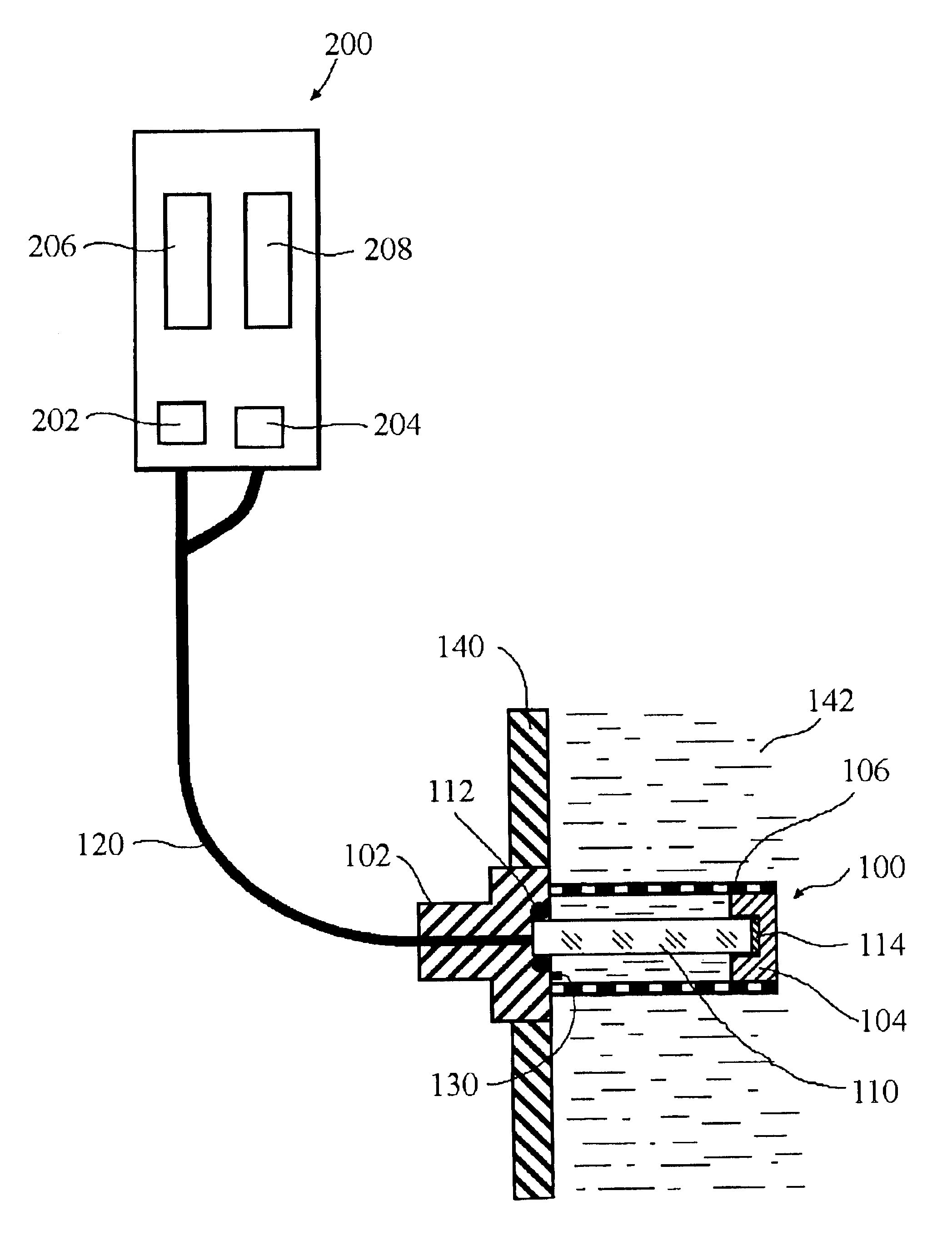
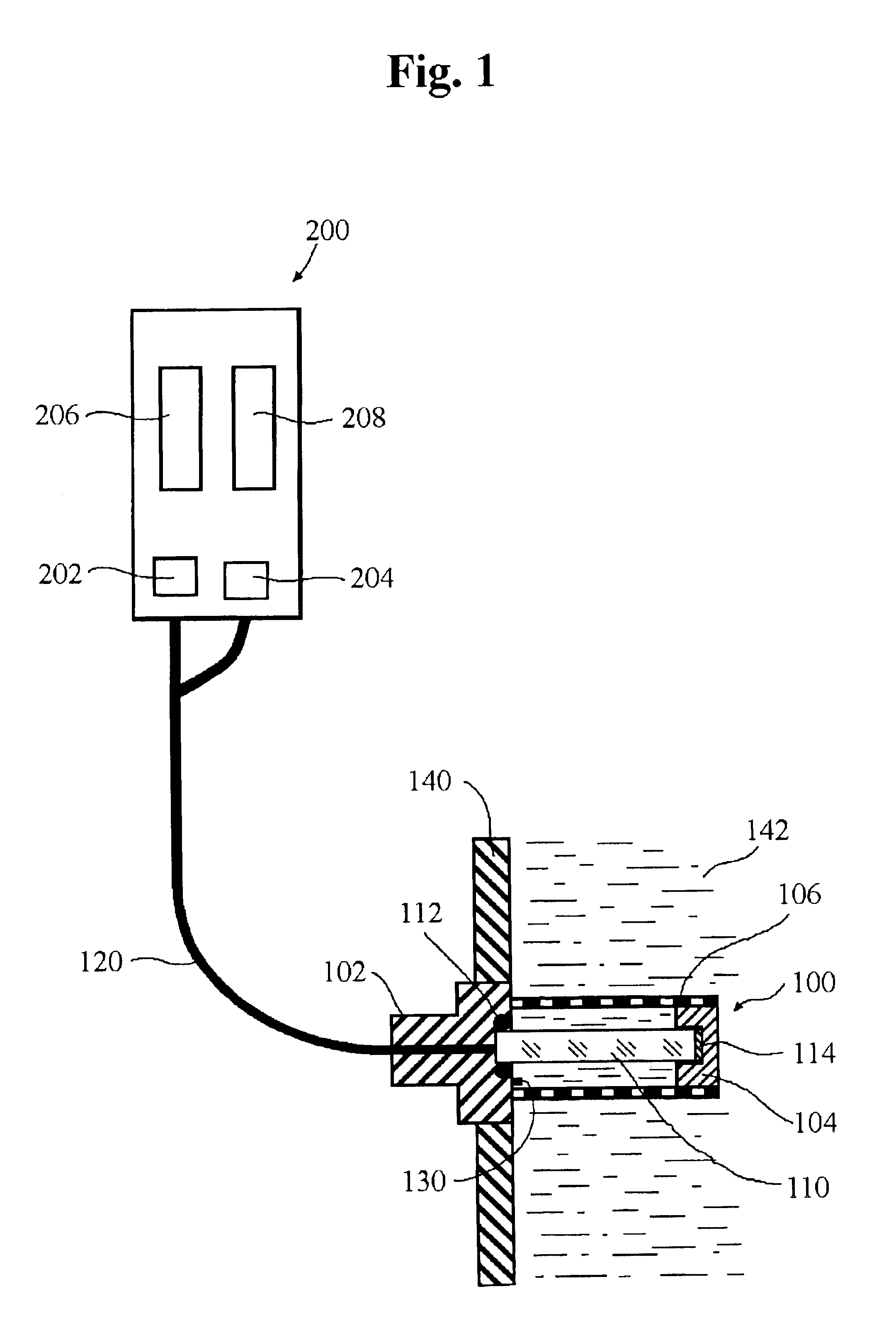
FIG. 1 shows an apparatus for measuring soot content in diesel engine oil in real time in accordance with a preferred embodiment of the present invention, and FIG. 2 is a sectional view showing a sensing portion and a light transmission portion of the apparatus depicted in FIG. 1.

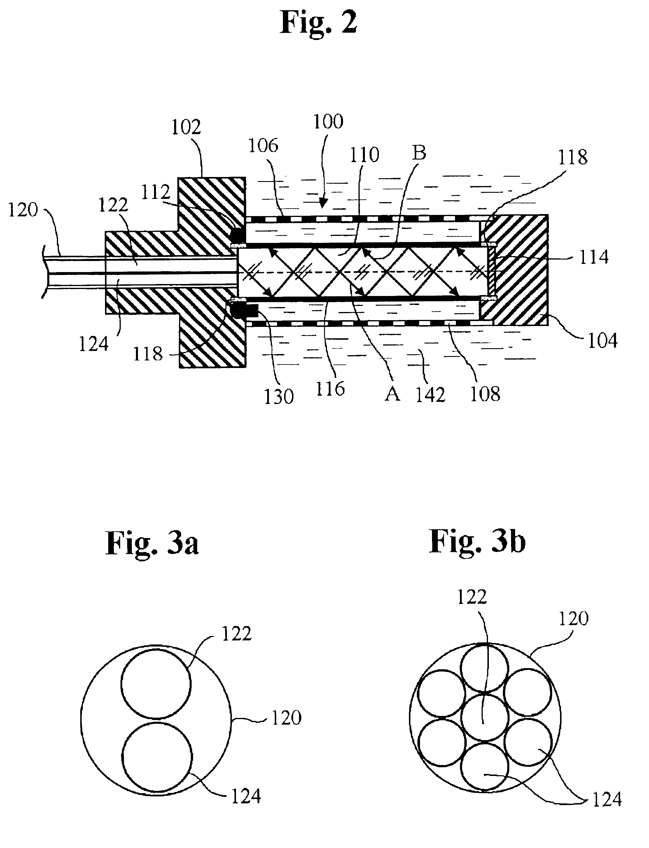
As shown in the drawings, the inventive apparatus for measuring soot content in diesel engine oil in real time comprises a sensing portion 100 which is mounted in a container 140 storing diesel engine oil 142, a signal processing portion 200 which processes a signal corresponding to the light passing through the sensing portion 100, and a light transmission portion 120 which transmits the light between the sensing portion 100 and the signal processing portion 200.

The signal processing portion 200 includes a light-emitting portion 202 which emits the light toward the sensing portion 100, a light-r...


PUM

PropertyMeasurementUnit
frequencyaaaaaaaaaa
temperatureaaaaaaaaaa
refractive indexaaaaaaaaaa

Abstract

An apparatus for measuring soot content in diesel engine oil in real time comprises an optical rod capable of transmitting light and having a boundary surface adapted to be in contact with the diesel engine oil and first and second end portions, a light-emitting portion, and a first optical fiber connected to the light-emitting means. The first optical fiber is adapted to transmit light from the light-emitting means to the first end portion of the optical rod in an aperture angle of the optical fiber to the boundary surface. The apparatus also comprises a light-receiving portion adapted to receive light from the optical rod and output a signal corresponding to the received light power. The refractive index of the optical rod is larger than the refractive index of the diesel engine oil. The aperture angle of the optical fiber is equal to or larger than a critical angle reduced to air at which the light is totally reflected by the boundary surface.

Description

FIELD OF THE INVENTIONThe present invention relates to an apparatus for measuring soot content in oil, and particularly to an apparatus for measuring soot content in diesel engine oil in real time by detecting a change of light power passing through an optical rod immersed in the oil, which is reflected by a boundary surface of the optical rod in contact with the oil containing carbon soots.BACKGROUND OF THE INVENTIONGenerally, the lifespan of engine oil depends on a running distance of a vehicle or operating time of the engine. As time passes, engine oil is oxidized or nitrified, and deteriorates by being mixed with carbon soots, metallic particles, fuel oil or coolant. Various apparatus for detecting engine oil deterioration are required, which are usually costly for both manufacturers and consumers. There is a need for a primary apparatus for detecting oil deterioration in an effective manner. When detecting diesel engine oil deterioration, measurement of carbon soot content in o...

Claims


Application Information

Patent Timeline
Patent Type & Authority Patents(United States)
IPC IPC(8): G01N33/00G01N21/43G01N21/41G01N21/15
CPCG01N33/2835G01N21/431G01N21/15
Inventor KONG, HOSUNGHAN, HUNG-GUYOON, EUI-SUNGMARKOVA, LYUBOV VASILIEVNASEMENYUK, MIKHAIL SAVICH
Owner KOREA INST OF SCI & TECH
Learn More