Capacitor charge balancing technique for a three-level PWM power converter

a technology of pwm power converter and capacitor, which is applied in the direction of dc-ac conversion without reversal, process and machine control, instruments, etc., can solve the problems of high voltage on some switches, voltage across the two capacitors frequently becoming unbalanced, and dc components of current flowing into and out of the neutral nod

Inactive Publication Date: 2005-01-11
ROCKWELL AUTOMATION TECH
View PDF9 Cites 215 Cited by
  • Summary
  • Abstract
  • Description
  • Claims
  • Application Information

AI Technical Summary

Benefits of technology

[0016]A controller operates the DC to AC inverter to produce a sequence of output pulses having positive, zero and negative voltage levels in which a plurality of output pulses occur during each half-cycle of an oscillating waveform. The controlle

Problems solved by technology

However, the voltages across the two capacitors frequently become unbalanced during operation of a three-level inverter.
This imbalance results from DC components of current flowing into and out of the neutral node under transient conditions, such as when the load applied to the motor suddenly changes.
Any imbalance between the capacitor voltages could result in high voltage on

Method used


Image

  • Capacitor charge balancing technique for a three-level PWM power converter
  • Capacitor charge balancing technique for a three-level PWM power converter
  • Capacitor charge balancing technique for a three-level PWM power converter

Examples


Embodiment Construction

nt and its average value in the partial dipolar modulation mode of the present power converter;

[0039]FIG. 22 is a flow chart of an second version of a procedure according to the present invention for determining the capacitor voltage imbalance compensation coefficient;

[0040]FIGS. 23A and 23B graphically illustrate the relationship of signals at inputs of two comparators in the present power converter which utilizes the imbalance compensation procedure of FIG. 22;

[0041]FIGS. 24A, 24B, 24C and 24D depict control signals for semiconductor switches in one inverter phase branch as a result of the imbalance compensation procedure of FIG. 22;

[0042]FIG. 25 is a graph of the resultant phase to neutral voltage produced by the control signals in FIGS. 24A-D; and

[0043]FIG. 26 is a graph of the neutral current and its average value which result from the control signals in FIGS. 24A-D.

DETAILED DESCRIPTION OF THE INVENTION

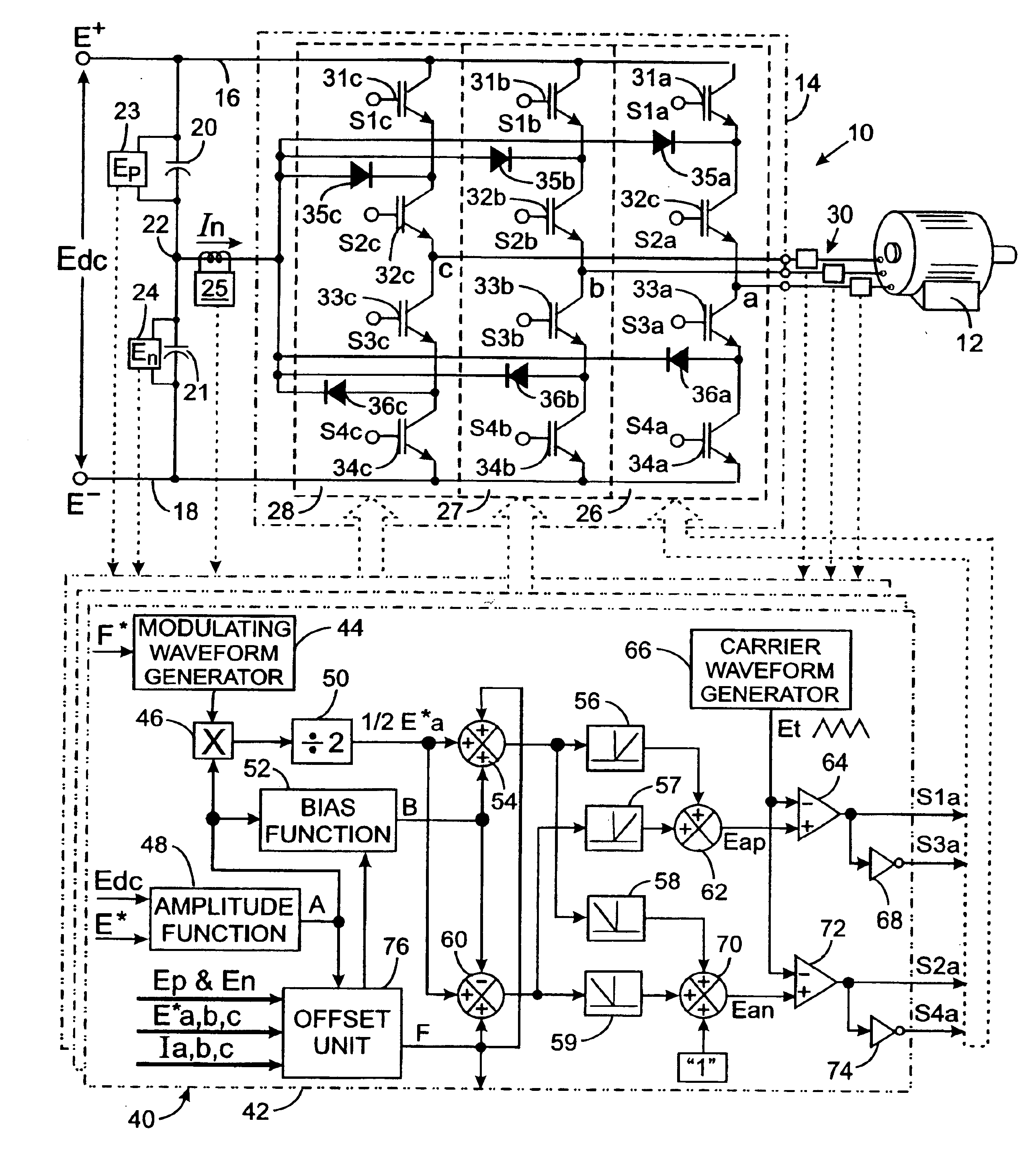
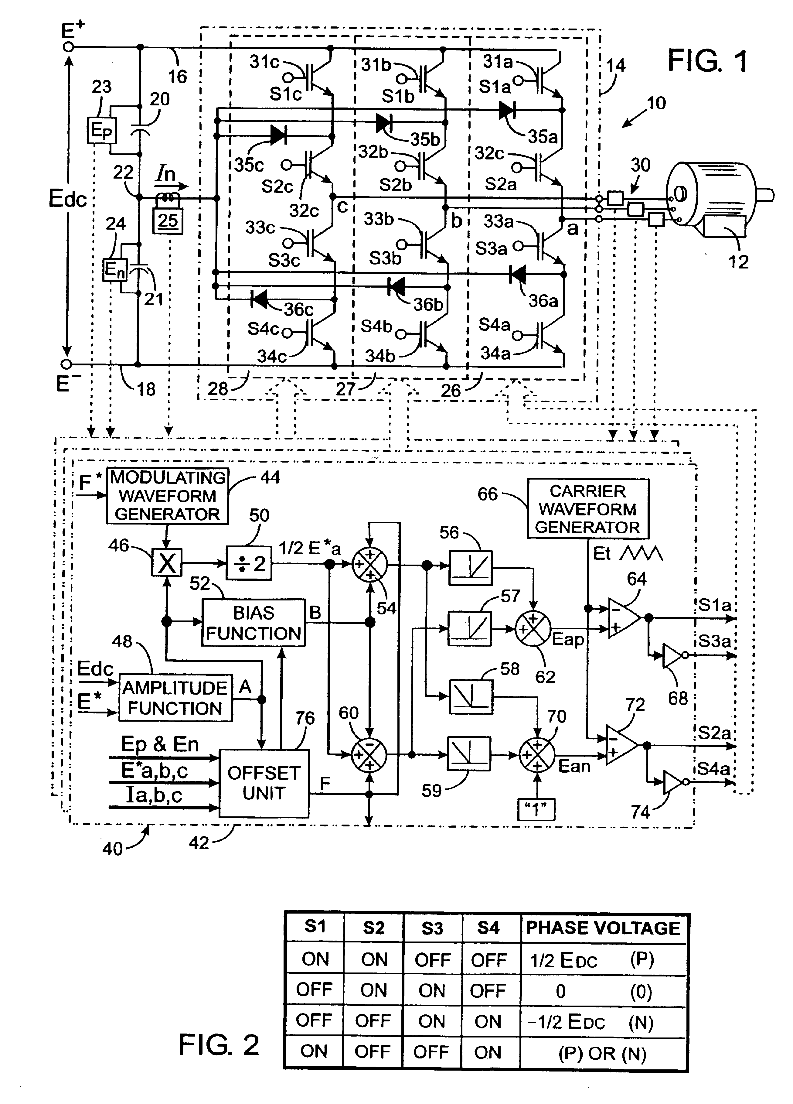
[0044]With initial reference to FIG. 1, a power converter 10 is provided to ...


PUM


Abstract

A power converter includes a DC to AC inverter that is connected to a neutral node formed between first and second capacitors connected across two DC supply lines. The inverter is operated to selectively couple the DC supply lines and the neutral node to an output terminal thereby producing an alternating voltage waveform formed by a sequence of output pulses having positive, zero and negative voltage levels. To compensate for a voltage imbalance across the capacitors, an imbalance compensation coefficient is derived from the difference in voltages across the first and second capacitors and from the direction of current between the neutral node and the inverter. The imbalance compensation coefficient is employed to adjust the width of the output pulses so as to charge and discharge the capacitors to correct the imbalance.

Description

CROSS-REFERENCE TO RELATED APPLICATIONS[0002]Not ApplicableSTATEMENT REGARDING FEDERALLY SPONSORED RESEARCH OR DEVELOPMENT[0003]Not ApplicableBACKGROUND OF THE INVENTION[0004]1. Field of the Invention[0005]The present invention relates to apparatus which convert a DC supply voltage into an alternating voltage; and more particularly to such apparatus, such as motor drives and power inverters, that control electricity supplied to an electric motor.[0006]2. Description of the Related Art[0007]Motor drives are commonly employed to control the application of electricity to a three-phase induction motor. Such motor drives include an inverter which switches DC voltage to output lines in a pulse width modulated (PWM) manner so as to control the frequency and amount of voltage applied to the motor and thus the motor speed.[0008]One type of an inverter, known as a two-level inverter, produces pulse width modulated (PWM) waveforms which have two voltage levels, formed by a positive voltage and...

Claims


Application Information

Patent Timeline
IPC IPC(8): H02M7/48H02M7/483H02M7/487
CPCH02M7/487H02M7/483H02M7/4833
Inventor TALLAM, RANGARAJAN M.NAIK, RAJENDRA
Owner ROCKWELL AUTOMATION TECH
Why Eureka
Try Eureka