
Drive control device and image forming apparatus including the same

a technology of drive control and image forming apparatus, which is applied in the direction of electrographic process apparatus, instruments, printing, etc., can solve the problems of inability to accurately control the movement or the speed of the movable member moving is apt to vary, and it is difficult to execute accurate control of the movement or the position of the movable member

Inactive Publication Date: 2005-01-11
RICOH KK
View PDF12 Cites 43 Cited by
  • Summary
  • Abstract
  • Description
  • Claims
  • Application Information

AI Technical Summary

Benefits of technology

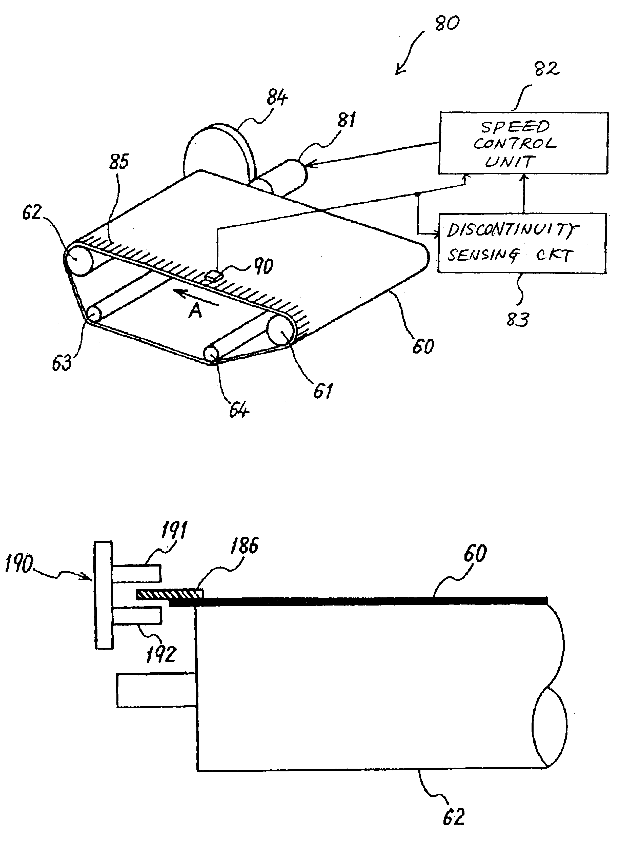
The present invention provides a device for controlling the drive of an endless movable member that can handle discontinuous portions in the marks on the movable member. The device includes a mark sensor, a speed / position controller, and a discontinuity sensing circuit. The discontinuity sensing circuit detects if there is a discontinuous portion in the sensing region of the mark sensor. The speed / position controller then adjusts the control of speed or position accordingly. This invention is useful for image forming apparatuses that require precise control over the movement of the movable member.

Problems solved by technology

In practice, however, the moving speed of the movable member is apt to vary due to various factors including a load exerted by a member contacting the movable member and cannot be fully controlled.
It is therefore difficult to execute accurate control over the movement or the position of the movable member.
However, the control device taught in the above document does not execute drive control on the basis of the movement or the position of the drum, which is the subject of control.
Accurate drive control is not available with the control device when a photoconductive belt or an intermediate image transfer belt or similar endless belt member is not directly connected to a drive shaft driven by a drive source.
However, it is extremely difficult to form marks on the belt member at preselected intervals although the document does not show or describe a mark forming method specifically.
Moreover, strain produced in the belt member after molding makes the contraction ratio and therefore the distance between nearby marks irregular.
When the marks are so put on the belt member after molding, the non-uniform contraction distribution of the belt member does not effect the distance between nearby belts.
Such a difference in circumferential length makes it extremely difficult to connect a seam portion between the beginning and the end of continuous marks such that the seam portion has the same interval as the continuous mark portion.
The discontinuous portion directly translates into a mark sensing error or unstable drive control.
At this instant, if a mark sensing error occurs or if mark sensing timing is noticeably shifted, then the phase of the reference signal and that of the comparison signal are noticeably shifted from each other, resulting in unstable control.
This problem arises even when the endless drive member to be controlled is implemented as a drum member.

Method used


Image

  • Drive control device and image forming apparatus including the same
  • Drive control device and image forming apparatus including the same
  • Drive control device and image forming apparatus including the same

Examples


modification 1

[Modification 1]

FIG. 11 shows Modification 1 of the illustrative embodiment. As shown, the drive control section includes a dummy signal generator or generating means 187 and a speed control unit or speed / position control means 182 in addition to the mark sensor 90 and discontinuity sensing circuit 83. The speed control unit 182 includes a PLL controller 183 similar to that of the illustrative embodiment and a signal selector or signal switching means 184. In Modification 1, the PLL controller 183 does not have to be ON / OFF controlled by an external signal and is therefore low cost.

The dummy signal generator 187 generates a dummy signal repeatedly appearing at a period identical with the mean interval of the mark sense signals derived from the continuous mark portion. More specifically, the dummy signal generator 187 samples a plurality of mark sense signals derived from the continuous mark portion, calculates a mean value over the sampling interval, and generates a dummy signal rep...

modification 2

[Modification 2]

Modification 2 will be described with reference to FIG. 13. In Modification 1 described above, the phase of the mark sense signal and that of the dummy signal are not matched to each other. This brings about a problem that if the two phases are shifted from each other, then the phase of the repeating pulse signal input to the PLL controller 183 is apt to jump for a moment in relation to the signal switching timing of the signal selector 184, causing the above phase to be noticeably shifted from the phase of the reference clock. Modification 2 is so configured as to reduce the jump of the phase of the repeating pulse signal input to the PLL controller 183, as will be described hereinafter.

As shown in FIG. 13, the drive control section includes a speed control unit or speed / position control means 282 in addition to the mark sensor 90 and discontinuity sensing circuit 83. The speed control unit 282 includes a speed calculator 287, a speed / frequency converter 288 and a p...

modification 3

[Modification 3]

Reference will be made to FIG. 14 for describing Modification 3 of the illustrative embodiment. As shown, a drive control section includes a speed control unit or speed / position control means 382 in addition to the mark sensor 90 and discontinuity sensing circuit 83. The speed control unit 382 includes a PPL controller 183, an F / V (frequency-to-voltage) converter 388, and a voltage control circuit 384. The controller 383 sends to the belt motor 81 a drive signal corresponding to the feedback signal derived from the mark sensor 90.

More specifically, the controller 383 includes a reference signal terminal to which a reference voltage or reference signal is input and a comparison signal terminal to which a voltage signal output from the voltage control circuit 384 is input. The reference voltage is matched to the target moving speed of the belt 60. The controller 383 compares the reference voltage and the voltage signal output from the voltage control circuit 384 and se...


PUM


Abstract

A device for controlling the drive of an endless movable member of the present invention includes a mark sensor responsive to a plurality of marks continuously positioned on the movable member at preselected intervals in the direction of movement of the movable member. A speed / position controller controls either one of speed and position by using the output of the mark sensor. A discontinuity sensing circuit determines whether or not a discontinuous portion in which a distance between nearby marks does not lie in a preselected range is present in a sensing region assigned to the mark sensor. The speed / position controller varies speed control or position control in accordance with the output of the discontinuity sensing circuit.

Description

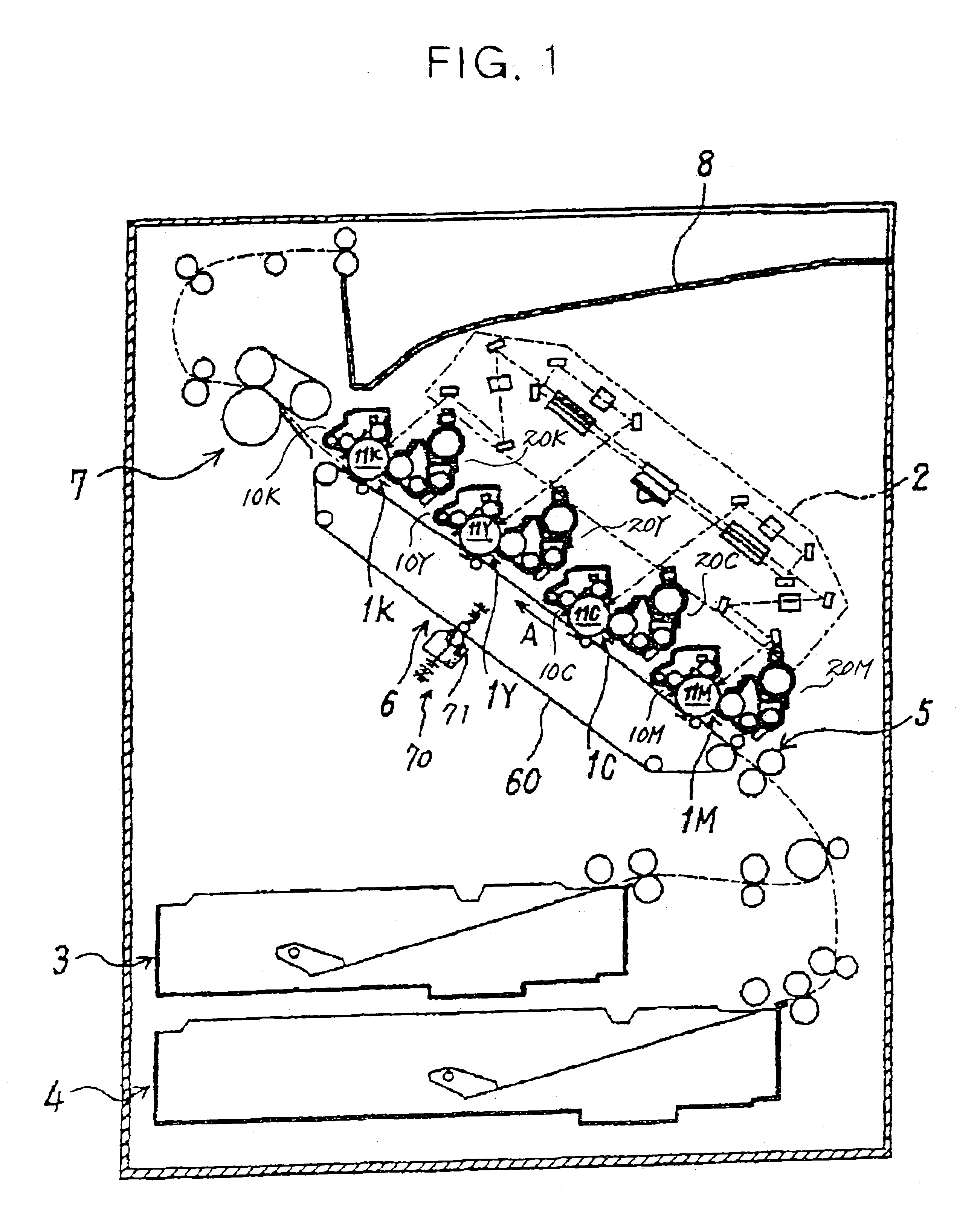
BACKGROUND OF THE INVENTION1. Field of the InventionThe present invention relates to a drive control device for causing an endless belt, drum member or similar endless movable member to perform adequate endless movement and a copier, printer, facsimile apparatus or similar image forming apparatus including the same.2. Description of the Background ArtA drive control device for the above application is customary with a photoconductive drum, intermediate image transfer belt or similar endless movable member joining in an image forming process. When such an endless movable member is driven, it is necessary to accurately position an image on the surface of the movable member or a sheet or recording medium being conveyed by the movable member. It follows that the movement of the movable member for a unit period of time or the preselected point of the movable member at a preselected time must be controlled with high accuracy. In practice, however, the moving speed of the movable member is...

Claims


Application Information

Patent Timeline
Patent Type & Authority Patents(United States)
IPC IPC(8): G03G15/00G03G15/16
CPCG03G15/757
Inventor KUDO, KOICHI
Owner RICOH KK
Learn More