Method for determining the leakage power for an integrated circuit

a leakage power and integrated circuit technology, applied in the direction of instruments, heat measurement, electric devices, etc., can solve the problems of large leakage current expected to become a major challenge, vdd fluctuations are very strong localities, and most methods for determining leakage have not taken these parameters into consideration

Inactive Publication Date: 2005-01-11
IBM CORP
View PDF3 Cites 84 Cited by
  • Summary
  • Abstract
  • Description
  • Claims
  • Application Information

AI Technical Summary

Problems solved by technology

With continuous shrinking of minimal feature size, leaky current is expected to become a major challenge for future complementary metal oxide silicon (CMOS) designs.
The increasing leakage current not only poses a problem for battery powered devices, such as mobile and hand-held electronics, it is increasingly critical for active operation as it is becoming a higher percentage of total power.
However, most methods for determining leakage have not taken these parameters into consideration.
However, in today's complex industrial designs, both temperature and Vdd fluctuations have very strong locality, i.e., they are not uniform across the chip.
Empirical methods in full chip leakage estimation are too simplistic, and thus inaccurate.

Method used


Image

  • Method for determining the leakage power for an integrated circuit
  • Method for determining the leakage power for an integrated circuit
  • Method for determining the leakage power for an integrated circuit

Examples


Embodiment Construction

In the following description, numerous specific details are set forth to provide a thorough understanding of the present invention. However, it will be obvious to those skilled in the art that the present invention may be practiced without such specific details. In other instances, well-known circuits may be shown in block diagram form in order not to obscure the present invention in unnecessary detail. For the most part, details concerning timing, data formats within communication protocols, and the like have been omitted inasmuch as such details are not necessary to obtain a complete understanding of the present invention and are within the skills of persons of ordinary skill in the relevant art.

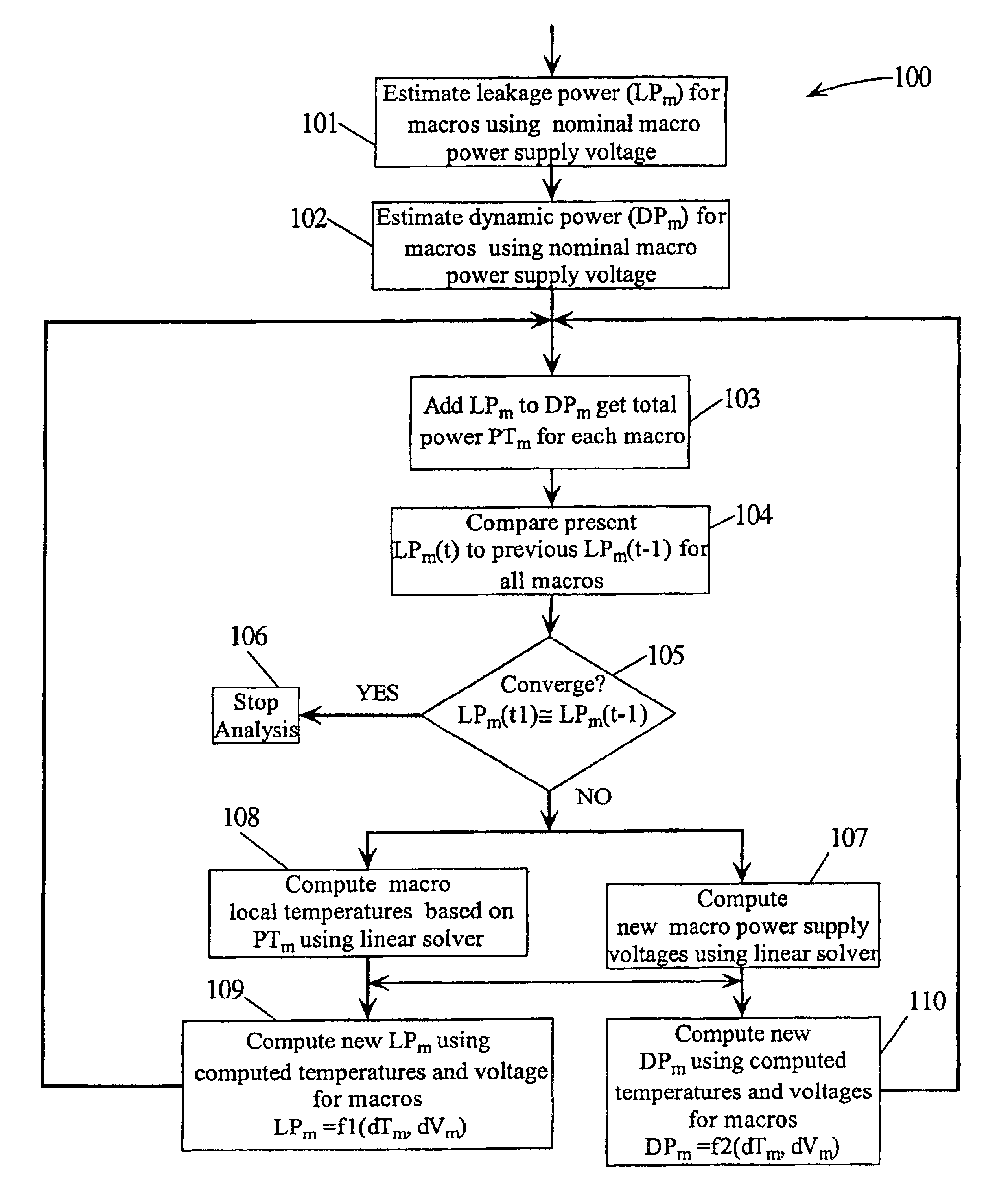
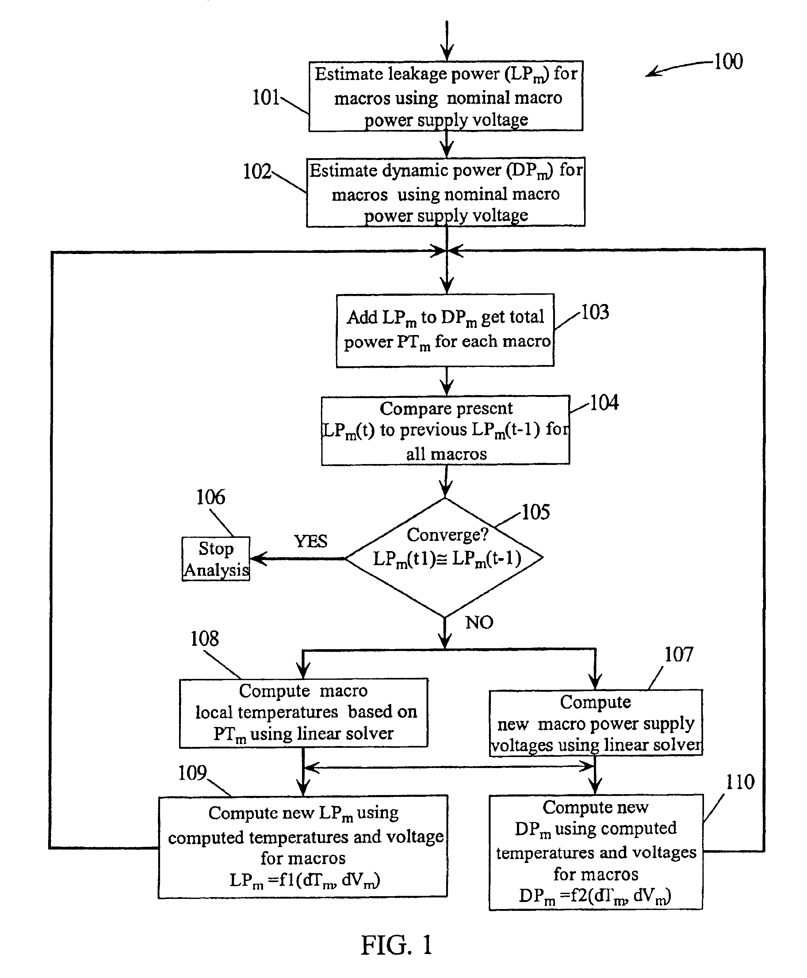
Refer now to the drawings wherein depicted elements are not necessarily shown to scale and wherein like or similar elements are designated by the same reference numeral through the several views. In the following, a convergence of an iteration means that the variable being calculated diffe...


PUM


Abstract

A method for determining full chip leakage power first estimates leakage power and dynamic power for each circuit macro. The power supply voltage to each macro is first assumed to be nominal. The power dissipation for each macro is modeled as a current source whose value is the estimated power divided by the nominal power supply voltage. The power distribution network is modeled as a resistive grids. The thermal environment of the IC and its electronic package are modeled as multi dimensional grids of thermal elements. Algebraic multi-grid (AMG) methods are used to calculate updated circuit macro voltages and temperatures. The macro voltages and temperatures are updated and updated leakage and dynamic power dissipation are calculated. Iterations are continued until leakage power converges to a final value.

Description

TECHNICAL FIELDThe present invention relates in general to methods and algorithms for determining the full chip leakage power of an integrated circuit (IC).BACKGROUND INFORMATIONWith continuous shrinking of minimal feature size, leaky current is expected to become a major challenge for future complementary metal oxide silicon (CMOS) designs. Although each is about 10% of total chip power for the current generation of CMOS technology, the number is expected to rise to 50% for next generation techniques. The increasing leakage current not only poses a problem for battery powered devices, such as mobile and hand-held electronics, it is increasingly critical for active operation as it is becoming a higher percentage of total power.Most of the leakage estimation and reduction techniques have focused on sub-threshold leakage due to the lowering of the power supply voltage and the accompanying reduction of the threshold voltage. With the reduction of the gate oxide thickness, the gate leak...

Claims


Application Information

Patent Timeline
Patent Type & Authority Patents(United States)
IPC IPC(8): G01R31/28G01R31/30
CPCG01R31/3008G01R31/3004
Inventor ACAR, EMRAHDEVGAN, ANIRUDHLIU, YINGNASSIF, SANI R.SU, HAIHUA
Owner IBM CORP
Why Eureka
Try Eureka