Component mounting method and component mounting apparatus

a technology for mounting methods and components, applied in metal working apparatuses, printed circuit manufacture, manufacturing tools, etc., can solve the problems of inefficient mounting methods, long mounting time, and prolonged mounting time, and achieve the effect of greatly shortening the mounting time of components

Inactive Publication Date: 2005-01-18
PANASONIC CORP
View PDF22 Cites 36 Cited by
  • Summary
  • Abstract
  • Description
  • Claims
  • Application Information

AI Technical Summary

Benefits of technology

With this component mounting apparatus, during placing components held by the component holding devices onto a circuit board, the components can be placed at desired positions on the board by moving the component holding devices vertically one time simultaneously by virtue of coincidence between the array intervals of the component holding devices of the transfer head and the intervals of the component placing positions on the board for the components held by the component holding devices. Thus, component mounting time can be greatly shortened.

Problems solved by technology

However, in a case of the step repeat method, since only one, from among the four suction nozzles, is used at all times, component suction and component placement are repetitively performed for every one component, causing mounting time to be prolonged.
Thus, this mounting method does not take full advantage of a multiple-head construction having a plurality of suction nozzles, resulting in an inefficient mounting method.
On the other hand, in a case of the pattern repeat method, since changing of suction nozzles is frequently performed, mounting time would be prolonged each time time-consuming nozzle changing work is performed a plurality of times. Thus, this method results in an inefficient mounting method.
Applying such a mounting method to recently increasing large-scale multiple boards composed of, for example, 50-200 boards would cause a mounting apparatus to operate quite tediously.
Besides, even if the array interval P of component feeders is equal to the array interval L of the suction nozzles, a shift of electronic components from an array line would make it not possible to achieve simultaneous suction.
Furthermore, any difference in component thickness would also make simultaneous suction of electronic components no longer achievable.
As a result, it would take a longer time to cause electronic components to be held by the suction nozzles, which has been an obstacle to reduction in mounting time.

Method used


Image

  • Component mounting method and component mounting apparatus
  • Component mounting method and component mounting apparatus
  • Component mounting method and component mounting apparatus

Examples


first embodiment

(First Embodiment)

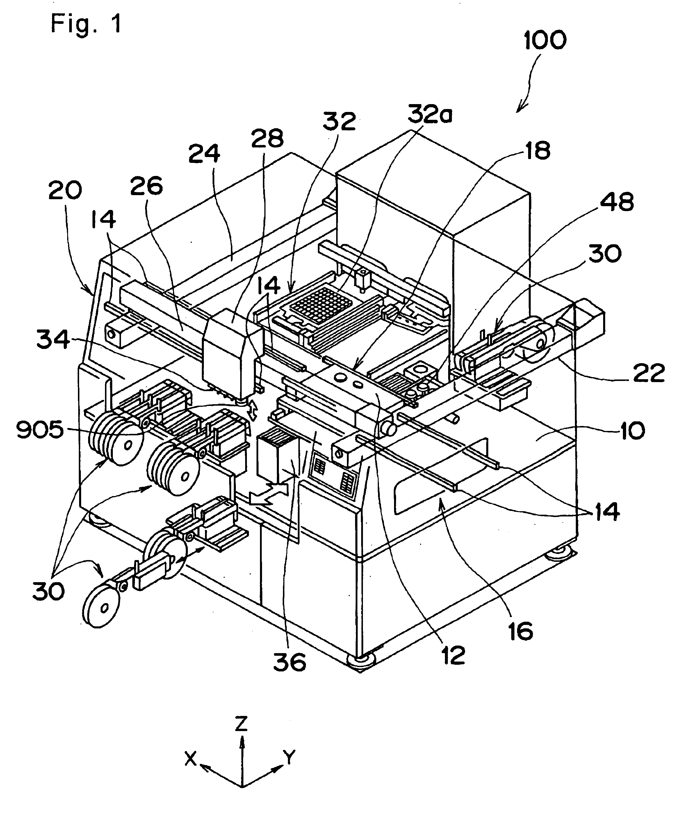
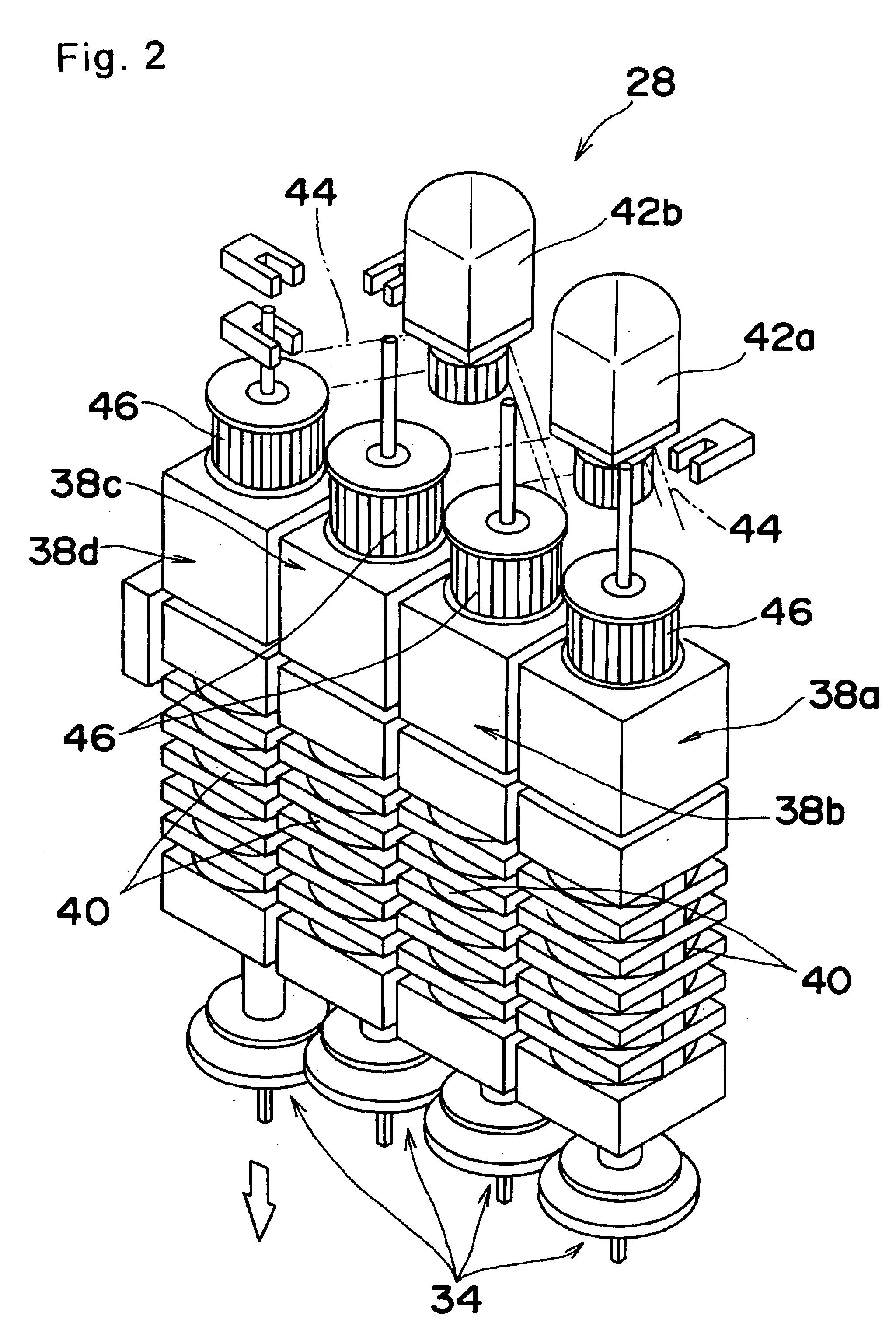
FIG. 1 is a perspective view of an electronic component mounting apparatus which is an example of the component mounting apparatus as a first embodiment of the present invention, FIG. 2 is an enlarged perspective view of a transfer head of the electronic component mounting apparatus of FIG. 1, and FIG. 3 is a schematic plan view of the electronic component mounting apparatus.

First, construction of an electronic component mounting apparatus 100 of the first embodiment is described.

As shown in FIG. 1, a pair of guide rails 14 for a circuit board 12 are provided at each of a loader section 16, a board holding section 18, and an unloader section 20 in a top center of a base 10 of the electronic component mounting apparatus 100. By synchronously driving transfer belts provided for each one of these pairs of guide rails 14, respectively, the circuit board 12 is transferred from the pair of guide rails 14 of the loader section 16 on one end side to the pair of guide rails...

example 1

First, a mounting operation performed by a task repeat method is described as Example 1. The task repeat method refers to a method of repeating a number of times, corresponding to patterns, a task of sucking components with a plurality of placement heads simultaneously, or individually, and then after recognition, placing all the components held on the placement heads onto the circuit board 12 simultaneously or individually.

FIG. 4 shows an example of a multiple board composed of three sub-boards of an identical pattern for explanation's sake, where it is assumed that chip components C1-C12, SOP1-SOP3, and QFP1-QFP3 are to be placed onto the pattern (first, second and third patterns) of each sub-board of this multiple board.

According to this mounting method, mounting of the electronic components is performed in an order of chip components to SOPs to QFPs as shown by arrows in FIG. 4. More specifically, as placement steps are shown sequentially in FIG. 5, first steps include sucking c...

example 2

Next, a mounting operation by an improved step repeat method is described as Example 2.

In this improved step repeat method, the order of mounting of electronic components is similar to that of a conventional step repeat method as shown in FIG. 7, where mounting is performed in order of chip components→SOPs→QFPs as shown by arrows in FIG. 7. More specifically, as placement steps are shown sequentially in FIG. 8, first steps include sucking chip component C1 to the first placement head 38a, chip component C5 to the second placement head 38b, and chip component C9 to the third placement head 38c by S-size suction nozzles, respectively, either simultaneously or individually, moving the transfer head 28, and placing the chip components C1, C5, C9 onto respective sub-boards in this order. Similarly, steps following this include sucking chip components C2, C6, C10 by the placement heads 38a, 38b, 38c, placing these components onto respective sub-boards, and further sucking and placing comp...


PUM

PropertyMeasurementUnit
speedaaaaaaaaaa
relative distancesaaaaaaaaaa
sizeaaaaaaaaaa

Abstract

An electronic component mounting method for placing electronic components successively to component placing positions on a board by component holding devices equipped with a plurality of removable suction nozzles which is operable to hold the electronic components. The method, as an example of its various manners, includes: in placing the electronic components onto a multiple board composed of a plurality of sub-boards, applying a placement step to all the sub-boards, the placement step being a step of placing onto the board all of electronic components that are holdable by an identical suction nozzle; and after completion of the placement step, changing the suction nozzle to another and moving to a next placement step, whereby electronic-component mounting for the individual sub-boards is carried out. In another aspect, component array intervals (M) of component feed sections or intervals (N) of component placing positions on the board are made coincident with array intervals (L) of the component holding devices.

Description

TECHNICAL FIELDThe present invention relates to a component mounting method and a component mounting apparatus for manufacturing circuit boards by placing a multiplicity of components onto a circuit board.BACKGROUND ARTIn recent years, needs for mounting apparatus for electronic components have been changing from rotary type high-speed mounters to robot type mounters that can flexibly be adapted to various forms of production, in terms of area productivity and component adaptability. Under such circumstances, for more improvement in productivity, those mounting apparatuses of which the number of placement heads to be mounted on one robot has evolved from one to many, and in which a suction nozzle to be used for each placement head is removable and interchangeable, have been forming a mainstream.In this type of electronic component mounting apparatus, there are some cases to use a so-called multiple board which is prepared by providing a plurality of circuits having an identical patt...

Claims


Application Information

Patent Timeline
Patent Type & Authority Patents(United States)
IPC IPC(8): H05K13/04
CPCH05K13/0408H05K13/0452H05K13/0478Y10T29/4913Y10T29/49144Y10T29/53178Y10T29/53174Y10T29/49131H05K13/0409H05K13/041
Inventor MAENISHI, YASUHIROINOUE, TAKAHIROYOSHIDA, IKUO
Owner PANASONIC CORP
Why Eureka
Try Eureka