

Apparatus for manufacturing a brake plate
a technology of brake plate and apparatus, which is applied in the field of brakes, can solve the problems of friction pad breaking, difficulty in attaching and/or retaining friction pads, and increasing costs
- Summary
- Abstract
- Description
- Claims
- Application Information
AI Technical Summary
Benefits of technology
Problems solved by technology
Method used
Image

Examples
Embodiment Construction
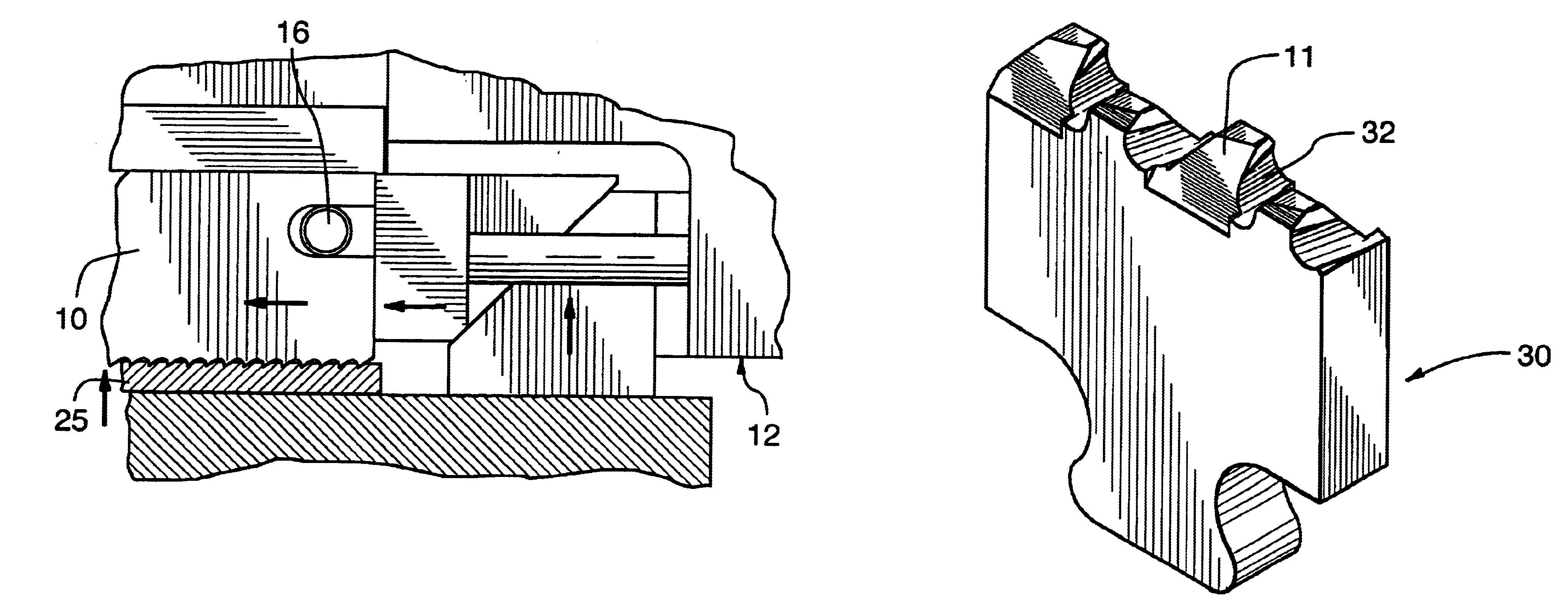
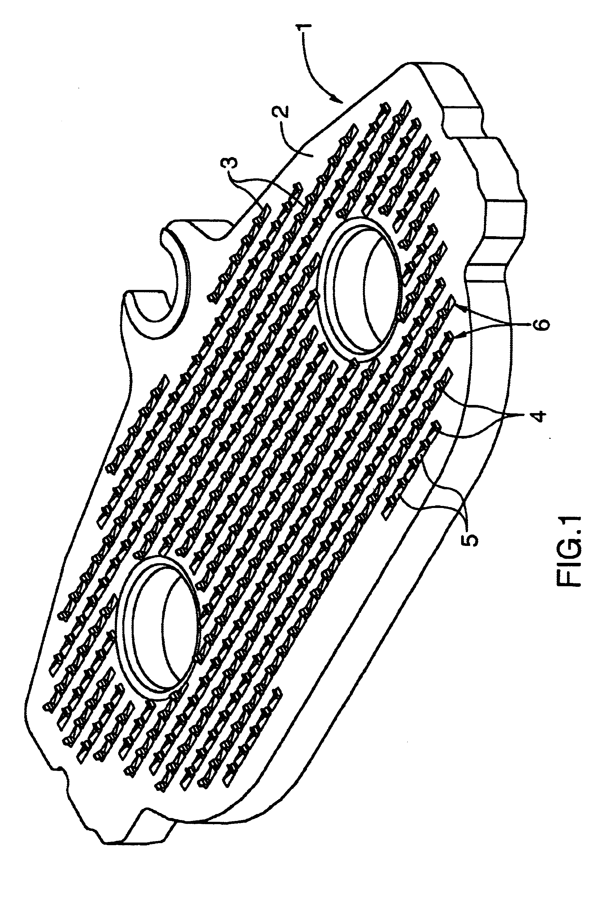
The invention is a plate for holding a friction material in a brake assembly. The plate preferably comprises:(a) a contact surface for attaching the friction material to the plate,(b) a second surface opposing the contact surface;(c) a plurality of retaining structures formed on the contact surface, each retaining structure comprising a projecting member extending from a point between the contact surface and the second surface, so that the member extends outwardly from the contact surface for engagement with the friction material.
The retaining structure may further comprise a depression surface abutting the projecting member, the depression surface extending into the contact surface.
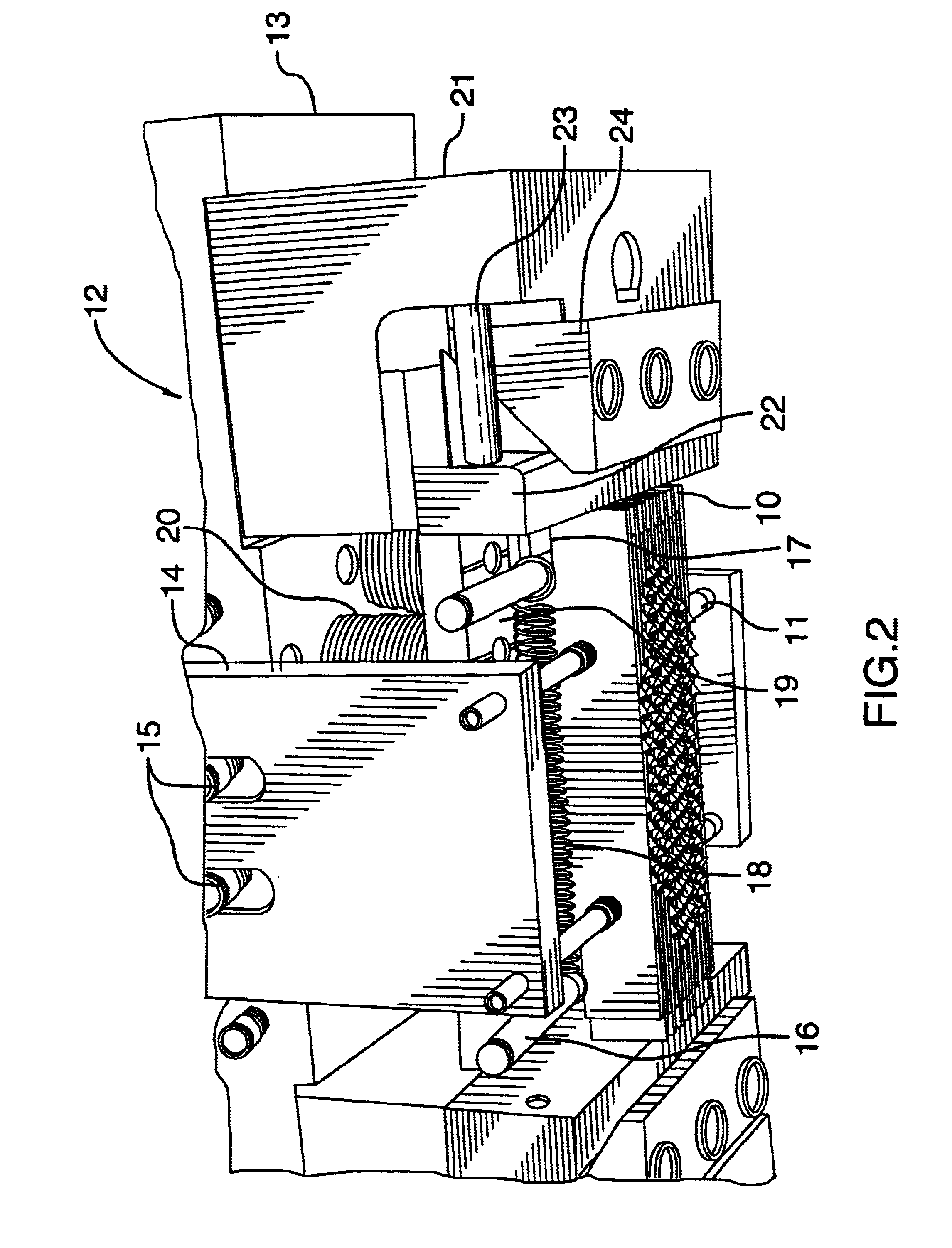
The brake plate, as well as the process and apparatus for manufacturing same according to the present invention are useful in the field of manufacturing of vehicle brake parts. The plate is useful in brakes for any motor vehicle, such as cars, trucks, airplanes, trains, bicycles, all terrain vehicles or ...
PUM
| Property | Measurement | Unit |
|---|---|---|
| height | aaaaa | aaaaa |
| distance | aaaaa | aaaaa |
| distance | aaaaa | aaaaa |
Abstract
Description
Claims
Application Information