Burner with oxygen and fuel mixing apparatus

a burner and fuel mixing technology, applied in the field of burner assemblies, to achieve the effect of lowering nitrogen oxide emissions

Inactive Publication Date: 2005-01-18
MAXON
View PDF10 Cites 42 Cited by
  • Summary
  • Abstract
  • Description
  • Claims
  • Application Information

AI Technical Summary

Benefits of technology

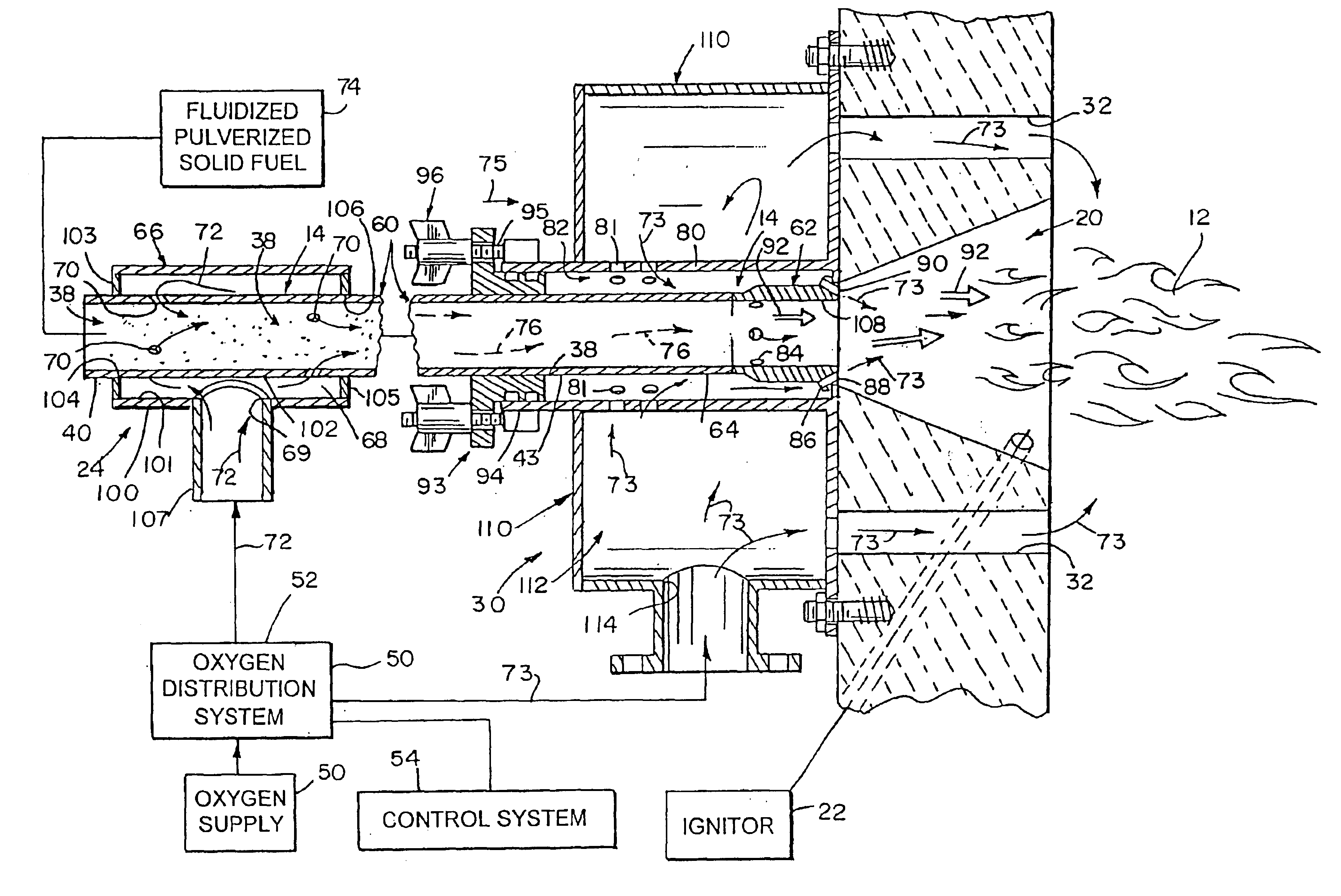
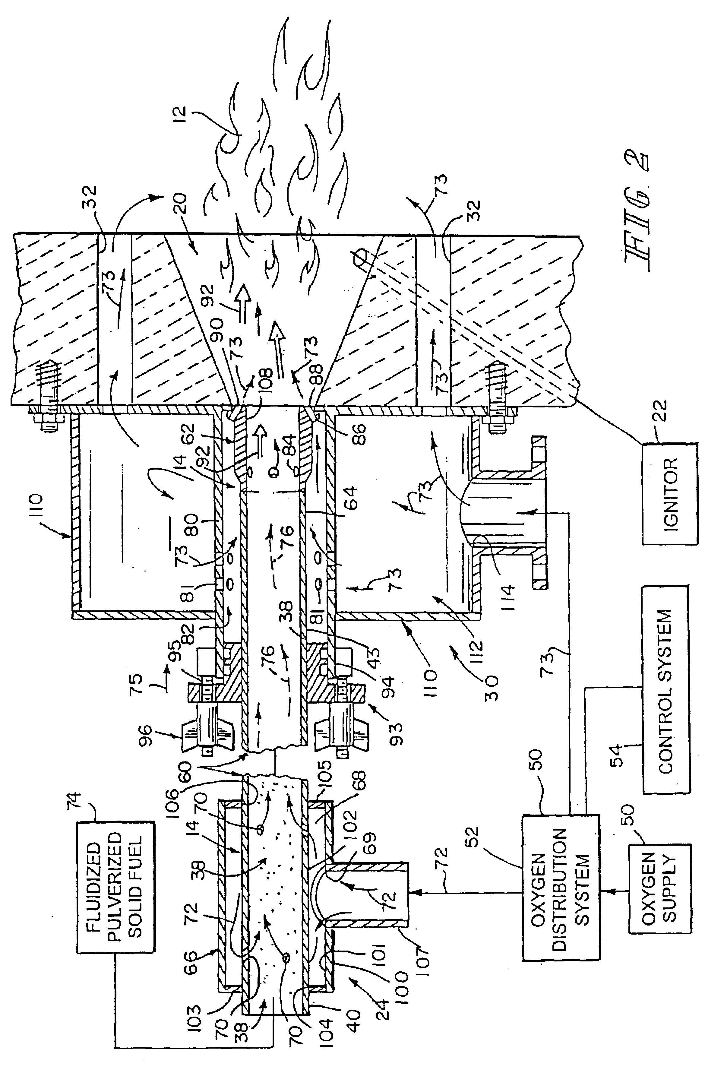
Also in the illustrated embodiment, the oxygen manifold is configured to communicate oxygen from the oxygen distribution system to the downstream portion of the fuel supply tube to produce a combustible oxygen-fuel mixture exiting the passageway to be ignited in the fuel-ignition zone to produce a flame. The oxygen manifold also is configured to communicate oxygen from the oxygen distribution system through one or more staged-oxygen bypass conduits to a portion of the flame outside the flame-ignition zone. Such “diversion” of combustion oxygen flow through the staged-oxygen bypass conduits to a region of the flame away from the root of the flame contributes to lowered nitrogen oxide emissions.

Problems solved by technology

One challenge facing the burner industry is to design an improved burner that produces lower nitrogen oxide emissions during operation than conventional burners.
Combustion of fuels such as natural gas, oil, liquid propane gas, low BTU gases, and pulverized coals often produce several unwanted emissions such as nitrogen oxides (NOx), carbon monoxide (CO), and unburned hydrocarbons (UHC).

Method used


Image

  • Burner with oxygen and fuel mixing apparatus
  • Burner with oxygen and fuel mixing apparatus
  • Burner with oxygen and fuel mixing apparatus

Examples


Embodiment Construction

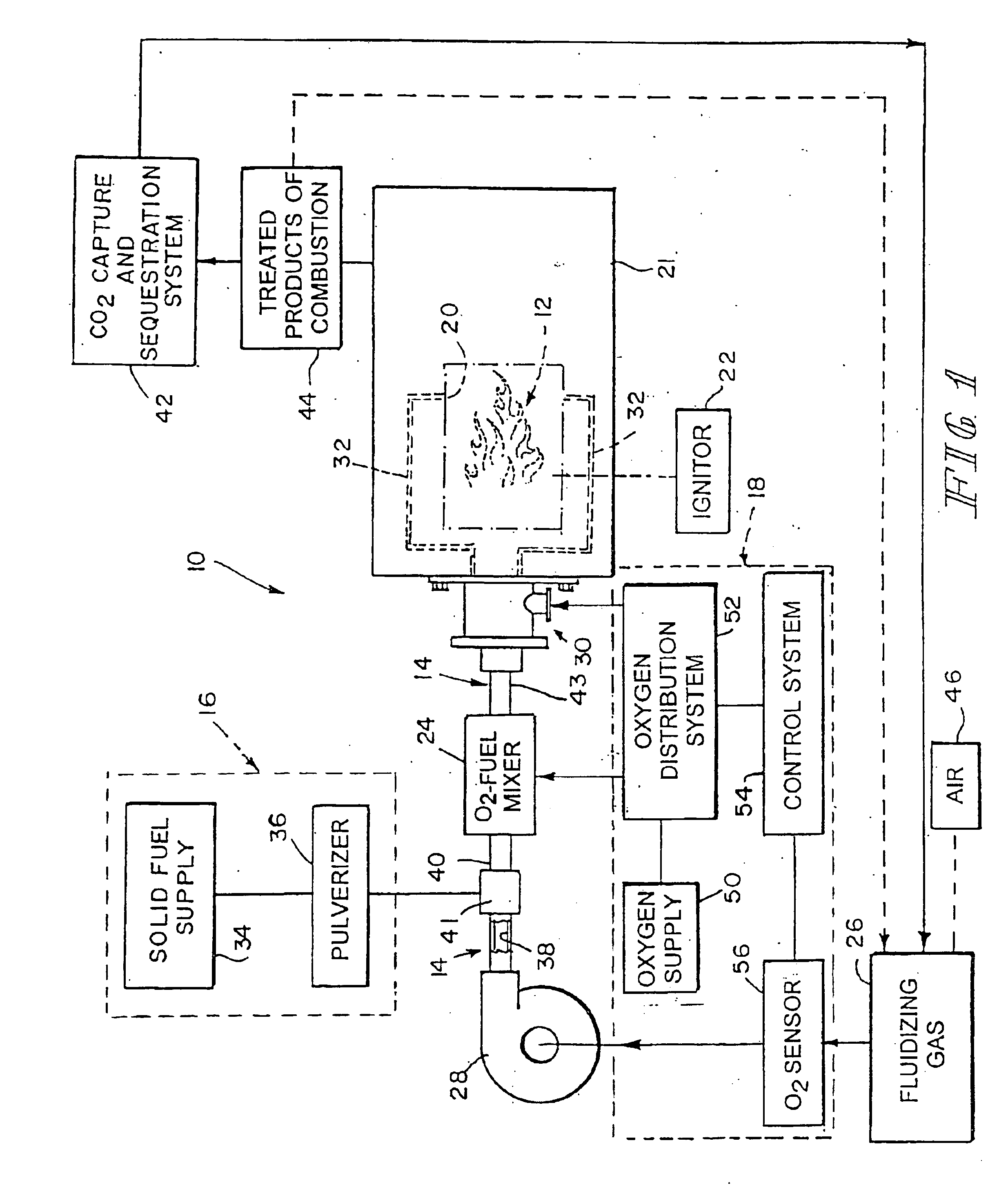
An oxygen-fuel combustion system 10 for burning a mixture of oxygen and a fluidized, pulverized, solid fuel to produce a flame 12 is shown schematically in FIG. 1. A fuel supply tube 14 conducts fuel provided by fuel delivery system 16 and oxygen provided by oxygen delivery system 18 to a flame chamber 20 provided in burner unit 21. An igniter 22 ignites the combustible oxygen-fuel mixture extant in a fuel-ignition zone provided by flame chamber 20 to produce flame 12. As used herein, “oxygen” means pure oxygen and any oxidant or oxygen-enriched mixture having an oxygen concentration of about 30% or more.

An oxygen-fuel mixer 24 is configured to mix oxygen supplied by oxygen delivery system 18 with a stream of pulverized, solid fuel supplied by fuel delivery system 16 and fluidized by fluidizing gas 26 discharged into fuel supply tube 14 using a blower 28 (or other suitable gas conveyance means). The oxygen-fuel transport mixture produced by mixer 24 is “designed” to be not spontaneo...


PUM


Abstract

An oxygen-fuel combustion system combines oxygen and fuel to produce a flame. The system distributes oxygen to a stream of fluidized, pulverized, solid fuel at various sites before and after ignition. The system is operable to vary the concentration of oxygen in an oxygen-fuel mixture extant at those sites.

Description

BACKGROUND AND SUMMARYThe present disclosure relates to burner assemblies, and particularly to oxygen-fuel burner assemblies configured to burn pulverized solid fuels. More particularly, the present disclosure relates to apparatus for mixing oxygen and fuel for use in a burner.Many types of coal and other solid fuels can be burned successfully in pulverized form. Coal is pulverized and delivered to fuel-burning equipment and then combusted in a furnace to produce heat for various industrial purposes.A burner is used to “fire” pulverized coal and other solid fuels. In a direct-firing system, the coal is delivered to the burner in suspension in a stream of primary air, and this mixture must be mixed with a stream of secondary air at the burner.One challenge facing the burner industry is to design an improved burner that produces lower nitrogen oxide emissions during operation than conventional burners. Typically, an industrial burner discharges a mixture of fuel and either air or oxyg...

Claims


Application Information

Patent Timeline
Patent Type & Authority Patents(United States)
IPC IPC(8): F23G5/033F23D1/00F23C9/00F23K3/00F23G5/02F23K3/02F23L7/00
CPCF23C9/003F23D1/00F23G5/033F23L7/007F23K3/02F23D2900/14002F23G2205/20Y02E20/344F23L2900/07005F23N2039/02Y02E20/322F23N2239/02Y02E20/34
Inventor TAYLOR, CURTIS L.
Owner MAXON
Why Eureka
Try Eureka