
Device for at least one milking stall and a parlor comprising a plurality of milking stalls

a technology of at least one milking stall and a plurality of milking stalls, which is applied in the direction of milking devices, catheters, animal husbandry, etc., can solve the problems of limited space available for different components of milking equipment and other equipment such as cleaning equipment, and achieve the effect of facilitating replacement and keeping production costs low

Inactive Publication Date: 2005-01-18
DELAVAL INC
View PDF5 Cites 8 Cited by
  • Summary
  • Abstract
  • Description
  • Claims
  • Application Information

AI Technical Summary

Benefits of technology

The object of the invention is to provide an improved cabinet-like structure, which also forms a part of the milking stall or a milking parlour. Hereby, the cabinet-like structure has to be robust and withstand forces from an animal being present in a milking stall. It is also desirable that most of the elements of the cabinet-like structure are of a modular construction so that they may be easily replaced if required and the production costs may be kept low.
According to a further embodiment of the invention, the cabinet-like structure comprises wall members of a material with thin wall thickness and the wall members extend in said substantially vertical direction and are attached to each other and form a hollow tube-like structure which surrounds said inner space. The wall members surrounding said inner space protect the different components, which are housed inside the cabinet-like structure. Moreover, since the wall members surround the inner space a cabinet-like structure is achieved which is easy to keep clean from the outside. The tube-like structure may have different shapes, in a cross sectional view seen along said longitudinal axis. However, the tube-like member is shaped so that it may resist forces from an animal being present in the milking stall.
According to a further embodiment of the invention, the cabinet-like structure comprises a substantially horizontal top plate which connects the wall members at the top portion, and a substantially horizontal bottom plate which connects the wall members at the bottom portion, wherein the cabinet-like structure forms an elongated hollow box-like structure which extends in said substantially vertical direction and which encloses said inner space. Owing to the top plate and the bottom plate a structure with good torsional rigidity is achieved. Moreover, since said top plate and said bottom plate together with said wall members enclose said inner space, the inner space is protected from dirt and dust from the outside environment. The bottom plate may be a part of said floor of the milking stall but the bottom plate may also be formed of a separate thin metal sheet, wherein the cabinet-like structure is attached to said floor via said thin metal sheet by screws or the like.
According to a further embodiment of the invention, the cabinet-like structure comprises a second door portion which is movable between a first position in which the cabinet-like structure forms a closed structure at least in said substantially vertical direction and a second position, wherein the door portion carries a cleaning device for cleaning the milking member which is possible to use in said second position. Such a cleaning device has means for receiving the teatcups of the milking member after the milking is finished and is connected to a conduit for the supply of cleaning liquid to the teatcups and the claw. By housing the cleaning device inside the cabinet-like structure when it is not in use, it is protected from dirt and dust from the outside environment. This is an advantage since good hygiene is very important when running a dairy farm. By housing the cleaning device inside the cabinet-like structure it is also protected from violence from the animals.
According to a further embodiment of the invention, one of said wall members comprises a continues thin sheet which is shaped in such a way that it surrounds a great part of said inner space. Consequently, said wall member may be produced by essentially one single piece of a sheet. According to one embodiment the sheet is shaped in such a way that it forms, in a cross-sectional view seen along said longitudinal axis, a rear wall portion and two side wall portions. The sheet, which preferably is a metal sheet, may be bent in order to form said rear wall portion and said side wall portions. The rear wall portion may be short in relation to the side wall portions. Moreover, each side wall portion may extend from the rear wall portion so that they form an angel, which is larger than 90° with the rear wall portion. Moreover, each side wall portion may be bent in said vertical direction at a distance from the outer end of each side wall portion in such a way that a plane, which extends along the surface of each of said outer side wall portion is perpendicular to a plane which is parallel to the surface of the rear wall portion. The length of each outer side wall portion, in a cross-sectional view seen along said longitudinal axis, may be shorter than the length of each side wall which extends directly from the rear wall portion, seen in said cross section. Since it may happen that an animal being present in the milking stall may push herself towards said outer side wall portion, it is an advantage that this outer side wall portion is short in order to withstand substantially radial forces from the animal. Moreover, it may happen that an animal being present in the milking stall may kick about. Hereby, it is an advantage that each side wall portion extends from the rear wall portion so that they form an angel, which is larger than 90° with the rear wall portion, since the leg of the animal may run along the surface of the side wall portion. According to one embodiment said support structural element arranged to strengthen the cabinet-like structure is attached to the outer end of said outer side wall portions.

Problems solved by technology

This results in that the space available for different components of the milking equipment and other equipment such as cleaning equipment is limited.

Method used


Image

  • Device for at least one milking stall and a parlor comprising a plurality of milking stalls
  • Device for at least one milking stall and a parlor comprising a plurality of milking stalls
  • Device for at least one milking stall and a parlor comprising a plurality of milking stalls

Examples


Embodiment Construction

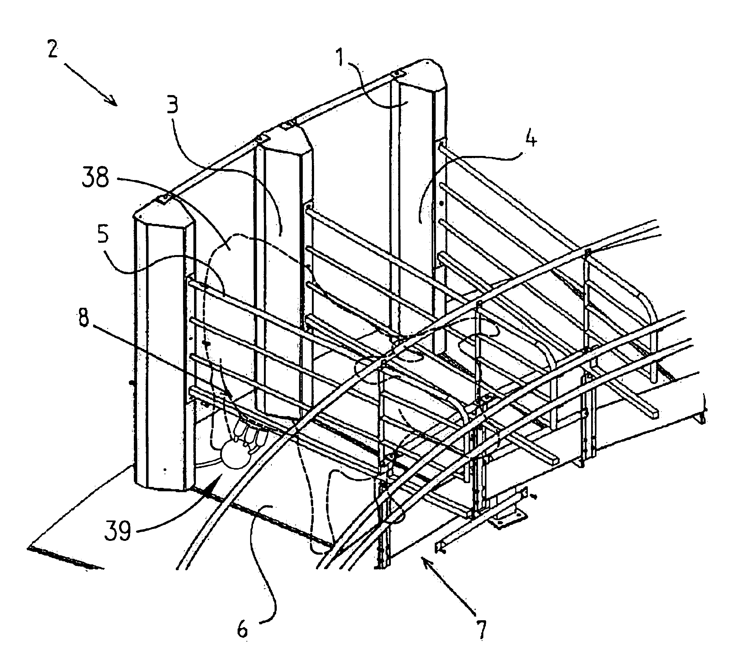
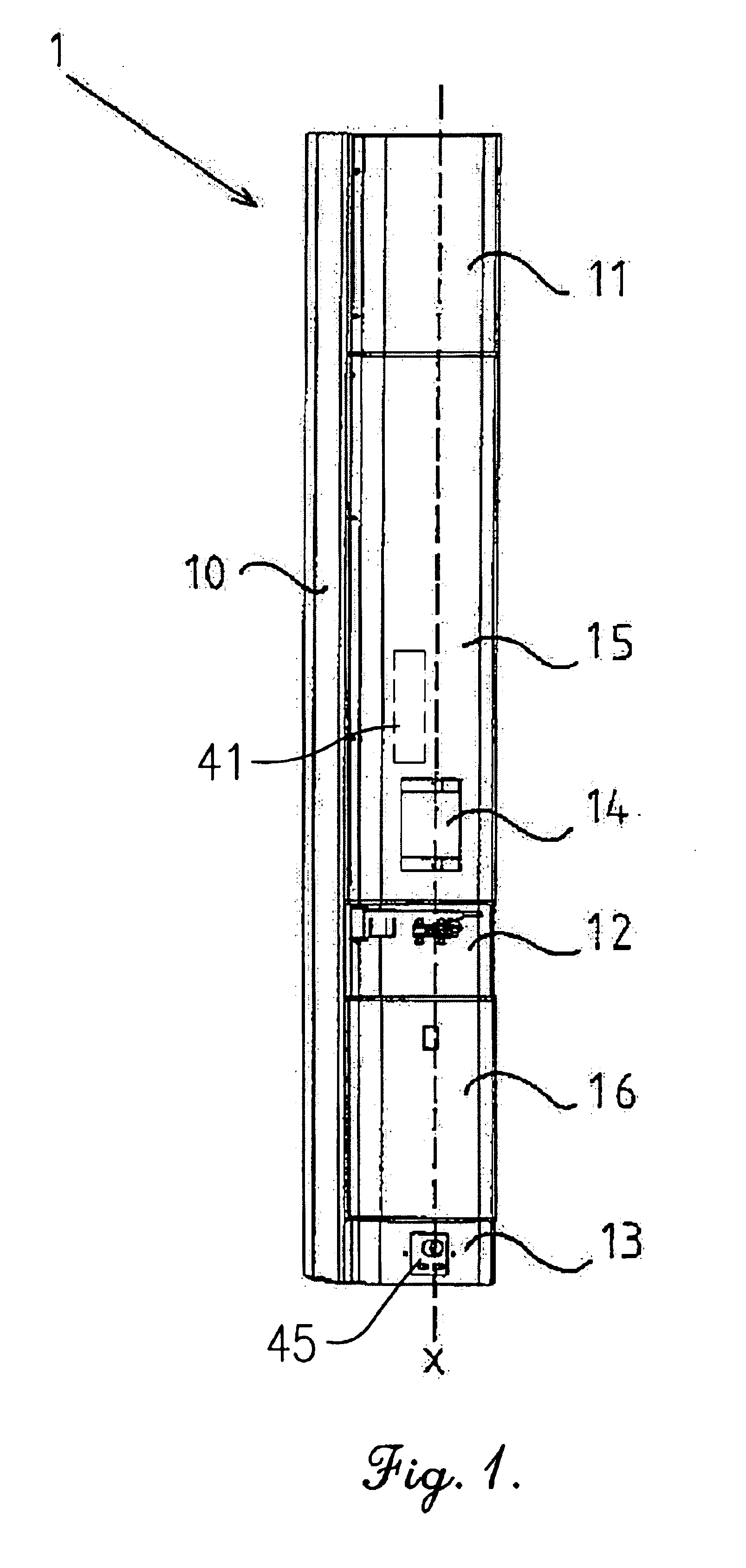
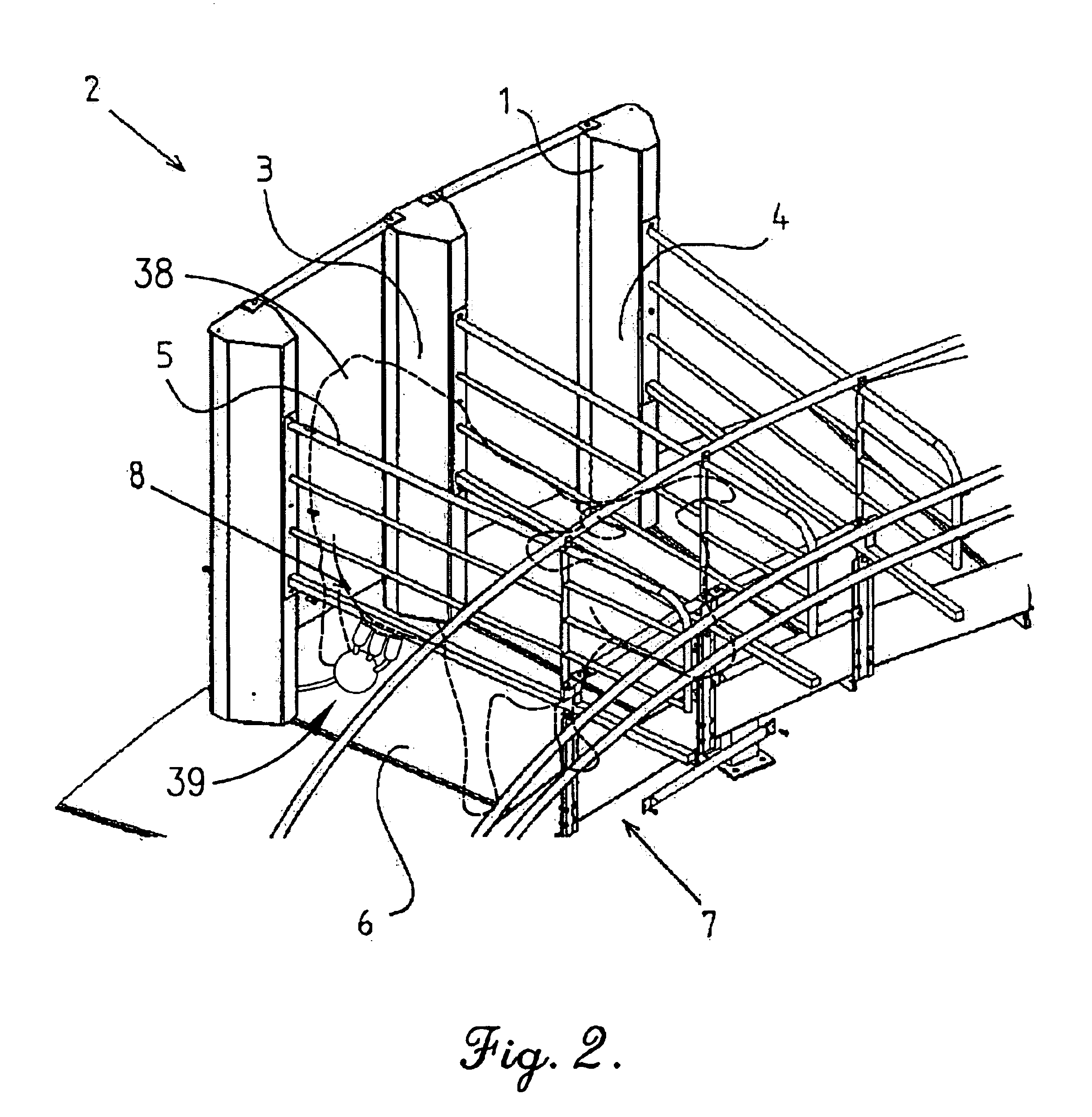
The device in FIG. 1 comprises a cabinet-like structure 1 which has a longitudinal axis x extending in a substantially vertical direction and which forms a building element of a milking parlour 2, which is shown in FIG. 2 and FIG. 3.

FIG. 2 shows a part of a rotary milking parlour 2 comprising a plurality of milking stalls 3 each of which is provided with a milking position 4 for an animal. Each milking stall 2 is defined by at least one wall arrangement 5 and a floor 6, and extends between a first end 7 and a second end 8. The wall arrangement 5 forms a side wall of two milking stalls 3 and extends between the first end 7 and the second end 8. Consequently, the wall arrangement 5 adjoins and separates two milking stalls 3 and the cabinet-like structure 1 carries the wall arrangement 5 at the second end 8 and is attached to the floor 6 of each milking stall 3 in question.

The cabinet-like structure 1 defines an inner space 9, shown in FIG. 4a and FIG. 4b, in which components of the mi...


PUM


Abstract

The invention refers to a device for at least one milking stall (3) with a milking position (4) for an animal and with at least one milking equipment including a milking member arranged to be attached to including animal for milking thereof. The milking stall (3) is defined by at least one wall arrangement (5) and a floor (6) and extends between a first end (7) and a second (8) end in such a way that when an animal is present in including milking stall (3) in including milking position, the front portion of including animal is adjacent including first end (7) and the back portion of including animal is adjacent including second end (8). The device includes a cabinet-like structure (1), which has a longitudinal axis extending in a substantially vertical direction and which defines an inner space and which forms a building element of including milking stall (3). The invention also refers to a parlour (2) including a plurality of milking stalls (3) and the cabinet-like structure (1) forms a building element of including parlour (2).

Description

TECHNICAL FIELD OF THE INVENTION AND PRIOR ARTThe present invention relates to a device for at least one milking stall according to the precharacterising portions of claim 1 and claim 27. The invention also refers to a parlour comprising a plurality of milking stalls according to the precharacterising portion of claim 24.In a conventional milking stall, there is a milking equipment with a lot of different components. These components comprise usually a milking member in the form of a number of teatcups which may be connected to a common claw, a long milk conduit connecting the claw to a milk-collecting member and to a vacuum source for transferring a milking vacuum to the teats, a holding member, or a so called service arm, for holding and supporting the long milk conduit, a pulsator arranged to provide a pulsating vacuum for a pulsating chamber in each teatcup, a remover for removing the milking member from the teats after the milking is finished, a control unit for controlling the...

Claims


Application Information

Patent Timeline
IPC IPC(8): A01K1/00A01K1/12
CPCA01K1/126A01K1/12
Inventor JOHANNESSON, LEIF BORJEOBERMULLER, HELMUT PETER PAUL
Owner DELAVAL INC
Learn More