Pneumatic tire for airplane with reinforcing layer having two or more joint portions in the circumferential direction

a technology of pneumatic tires and reinforcing layers, which is applied in the direction of aircrafts, transportation and packaging, yarn, etc., can solve the problems of destroying pneumatic tires for airplanes due to centrifugal force and scattering of tread pieces, and achieves a better hoop effect and easy absorbing

Inactive Publication Date: 2005-01-18
BRIDGESTONE CORP
View PDF2 Cites 4 Cited by
  • Summary
  • Abstract
  • Description
  • Claims
  • Application Information

AI Technical Summary

Benefits of technology

In accordance with the pneumatic tire for an airplane according to the seventh aspect, the following effect is achieved.
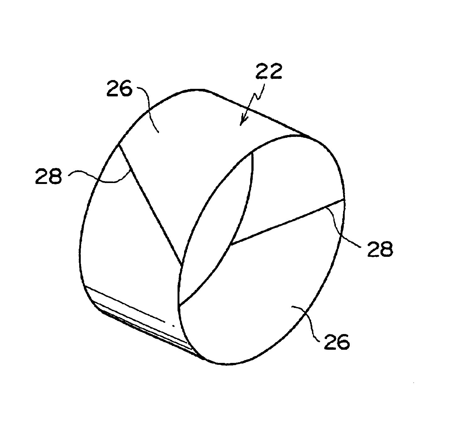
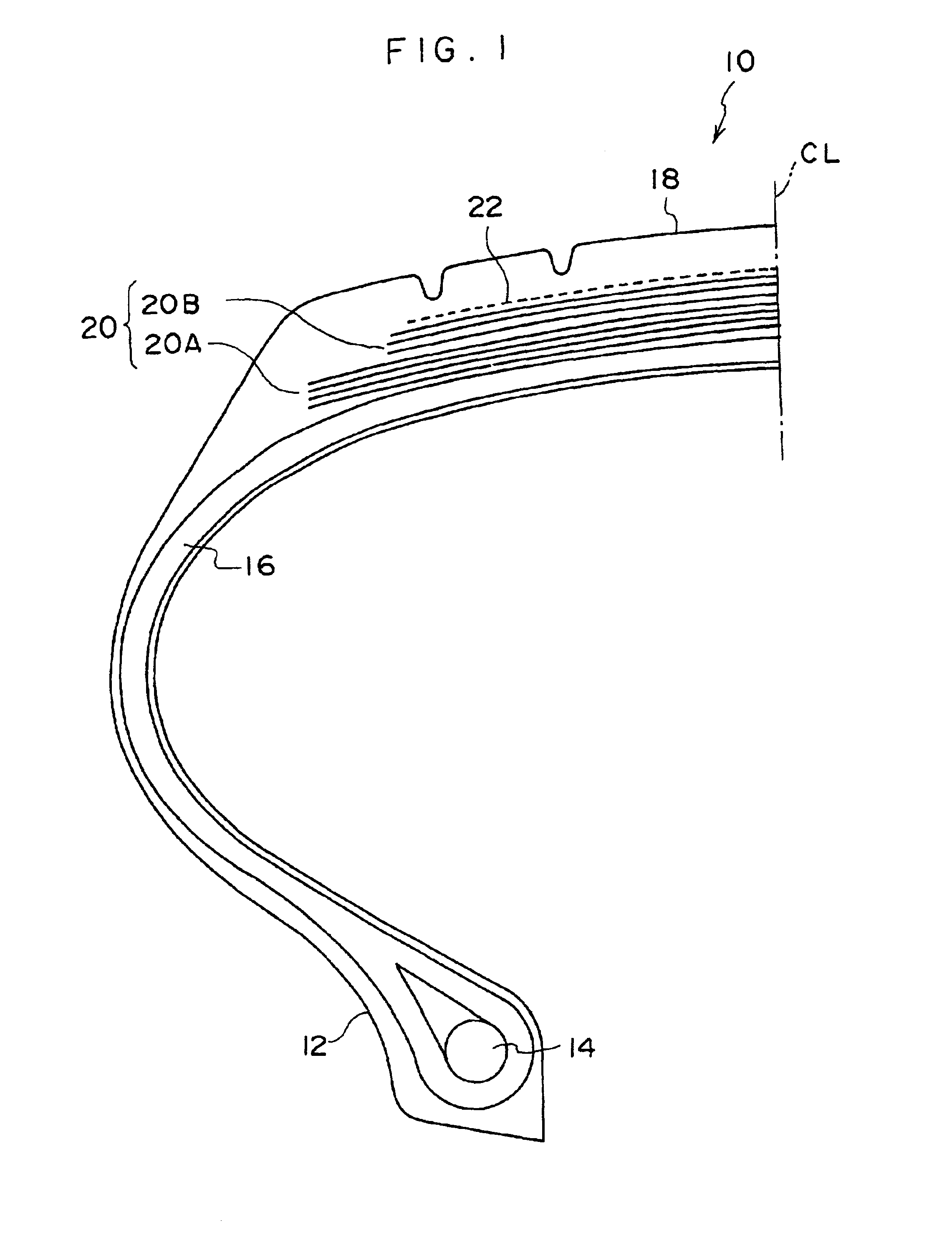
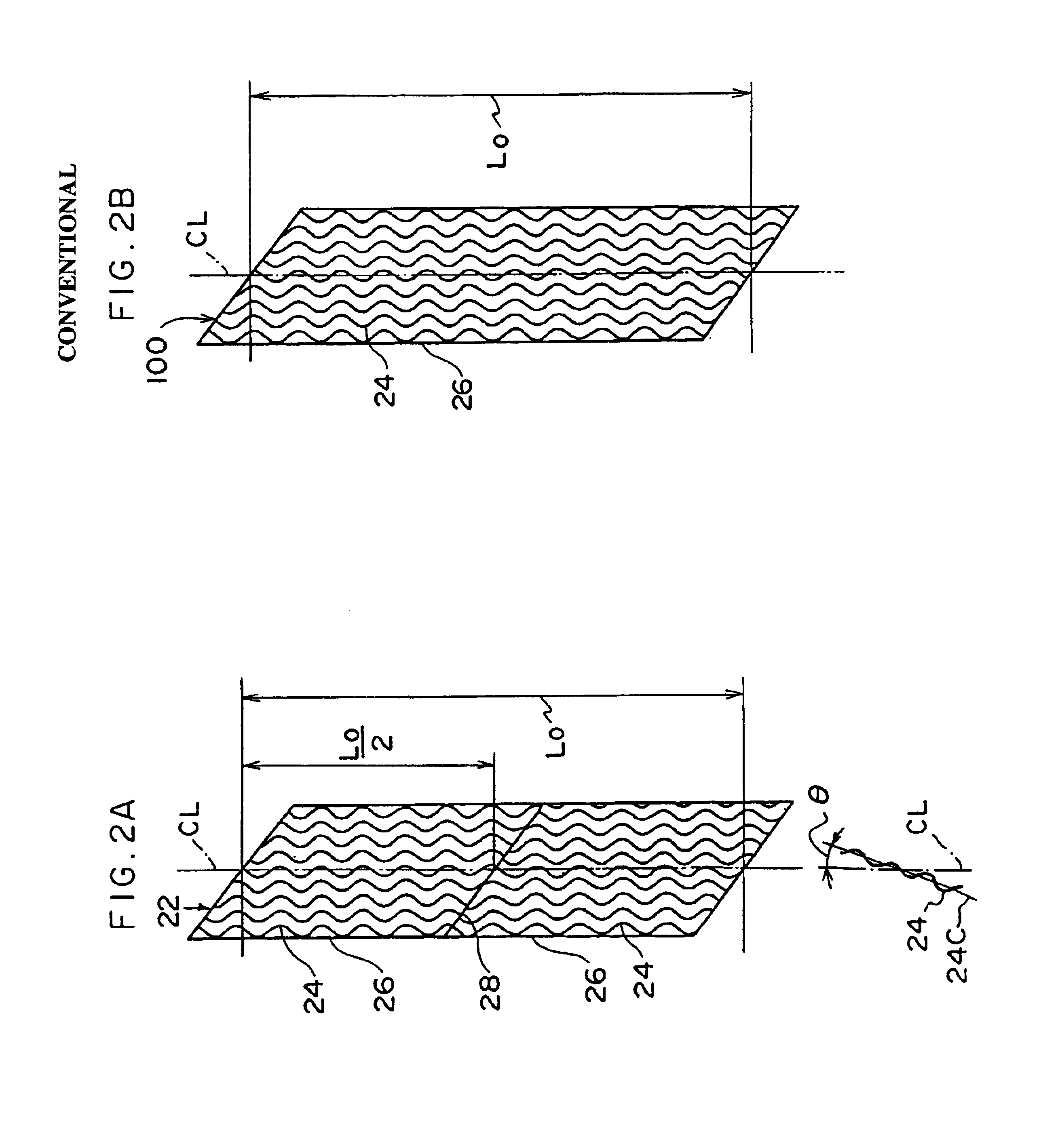
When the angle formed by the cords of the reinforcing layer with respect to the tire circumferential direction vary in the widthwise direction of the tire, e.g., when the aforementioned angle formed with respect to the tire circumferential direction is small in a vicinity of the tire equatorial plane CL and the angle changes so as to become greater, toward the longitudinal edges of the reinforcing layer, in the widthwise direction of the tire, deformation due to internal pressure, load and rotation is easily absorbed. Further, by this deformation, it is possible to apply tension to the cords themselves of the reinforcing layer, whereby a better hoop effect can be obtained.

Problems solved by technology

When an airplane travels at high speed on a pneumatic tire for an airplane which has been damaged or has burst due to external damage or the like while travelling, the pneumatic tire for an airplane may be destroyed due to centrifugal force, and the tread pieces may scatter about.

Method used


Image

  • Pneumatic tire for airplane with reinforcing layer having two or more joint portions in the circumferential direction
  • Pneumatic tire for airplane with reinforcing layer having two or more joint portions in the circumferential direction
  • Pneumatic tire for airplane with reinforcing layer having two or more joint portions in the circumferential direction

Examples


examples

In order to confirm the effects of the present invention, one Comparative Example tire, and three Example tires to which the present invention was applied were readied, and a drum test was carried out.

Test Tires: The structures, other than the reinforcing layers, of the tires were all the same. The reinforcing layers of the respective test tires were as shown in following Table 1.

Test Method: Under the following conditions, the test tires were set on the drum of a drum tester with a load applied on the tires, and were made to repeatedly travel such that the tires were forcibly broken. The size (length) of the largest tread piece in the tire circumferential direction which scattered was measured.

In each of the test tires, a cut, which was 100 mm in the widthwise direction of the tire and extended to the tire inner surface, was formed in advance in the center portion of the tread.

Tire Flexure: The tires were flexed to 50% of the height of the tire cross-section.

Speed: The tires were a...


PUM

PropertyMeasurementUnit
angleaaaaaaaaaa
distanceaaaaaaaaaa
angleaaaaaaaaaa

Abstract

In a pneumatic tire for an airplane of the present invention, a reinforcing layer, which is disposed at an outer side, in the radial direction of the tire, of a belt, includes plural cords, the cords being provided such that the longitudinal direction thereof forms an angle of substantially 15° or less with respect to a tire circumferential direction. The reinforcing layer has two or more joint portions in the circumferential direction of the tire. In accordance with the present invention, a length of the cords forming the reinforcing layer in the tire circumferential direction can be made short, whereby a size (length) of tread pieces formed at a time when the tire is damaged can be made small and damage caused to an airplane can be reduced.

Description

BACKGROUND OF THE INVENTION1. Field of the InventionThe present invention relates to a pneumatic tire for an airplane which is used on an airplane such as a jet passenger airplane or the like.2. Description of the Related ArtHigh-speed traveling on runways is required of pneumatic tires for airplanes. Thus, in order to further strengthen the hoop effect of a belt layer, a reinforcing layer which includes a plurality of cords is provided at the outer side of the belt layer in the tire radial direction.In order to strengthen the hoop effect of the belt layer even more, it is preferable to form the belt layer such that the angle formed by the cords of the reinforcing layer with respect to the tire circumferential direction is substantially 15° or less.Further, in order to eliminate the cut-ends of the cords of the reinforcing layer, it is preferable to use a reinforcing layer in which the cord direction is substantially the circumferential direction (a so-called spiral structure or joi...

Claims


Application Information

Patent Timeline
Patent Type & Authority Patents(United States)
IPC IPC(8): B60C9/22B60C9/20B60C19/00B60C9/18
CPCB60C9/20B60C9/22Y10T152/10765Y10T152/10801Y10T152/10783B60C2200/02
Inventor TOGO, HIROYUKI
Owner BRIDGESTONE CORP
Why Eureka
Try Eureka