High-speed spindle unit for machine tools

a high-speed spindle and machine tool technology, applied in the direction of turning machine accessories, metal-working apparatuses, chucks, etc., can solve the problem of strong heating of paired frictional surfaces

Inactive Publication Date: 2005-01-18
DECKEL MAHO PFRONTEN GMBH
View PDF7 Cites 10 Cited by
  • Summary
  • Abstract
  • Description
  • Claims
  • Application Information

AI Technical Summary

Benefits of technology

It is an object of the invention to provide a high-speed spindle unit in which a deterioration of the front bearings of the spindle, due to mechanical peak loads as well as damage caused by overload, can largely be avoided.

Problems solved by technology

Only after the gap has fully closed under a heavy load is there a pressure contact between the rotating rear face of the ring nut and the front face section of the stationary terminating ring of the housing, which results in a strong heating of the paired frictional surfaces.

Method used


Image

  • High-speed spindle unit for machine tools
  • High-speed spindle unit for machine tools
  • High-speed spindle unit for machine tools

Examples


Embodiment Construction

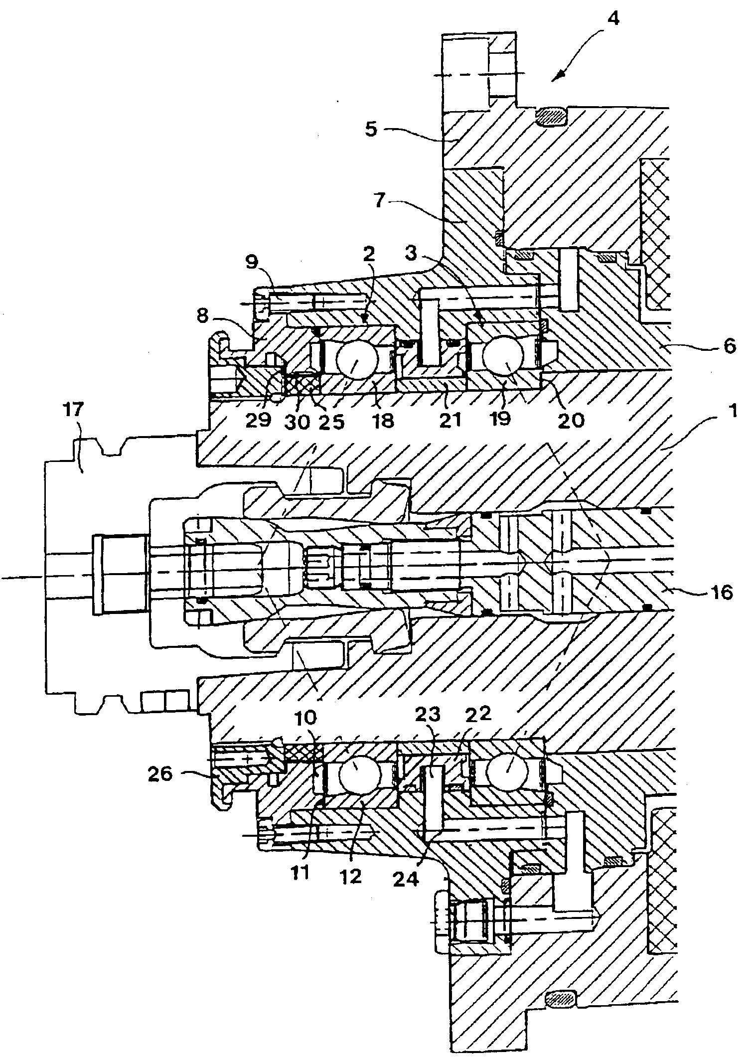
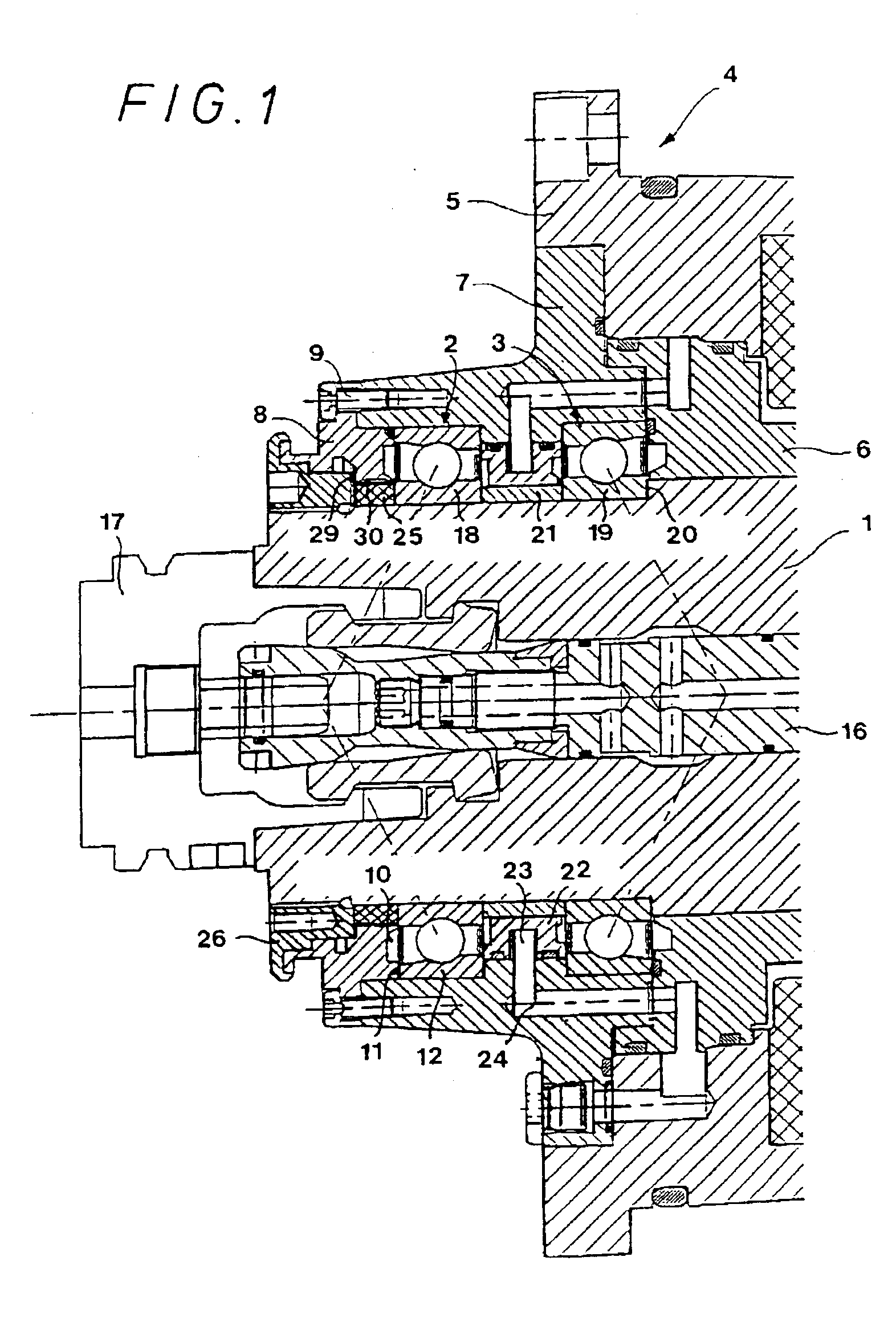
The high-speed spindle unit shown comprises a spindle 1 driven on its rear side by a drive unit (not shown), the front end portion of the spindle being supported in two roller bearings 2 and 3 arranged in a row within a multiple-component housing 4. Housing 4 comprises outer spindle housing 5 in which housing portion 6 and front bearing housing 7 are accommodated. Terminating ring 8 of the housing, having a profiled cross section, is fixed to the front face of bearing housing 7 by means of screws. The terminating ring of the housing is provided with central ring groove 10 on its radial rear face, which faces front roller bearing 2. The radially outer portion 11 of the ring groove is supported by stationary outer bearing race 12 of roller bearing 2. As can be seen in FIG. 2, the front portion of terminating ring 8 of the housing is formed with stepped radial front surfaces 13, 14, and 15.

In a central bore of spindle 1, collet chuck 16 is provided for clamping tool holder 17 in the fr...


PUM

PropertyMeasurementUnit
radial widthsaaaaaaaaaa
axial widthaaaaaaaaaa
gap widthsaaaaaaaaaa

Abstract

A high-speed spindle unit for milling and drilling machines. The spindle unit has a spindle housing on the front end portion of which a terminating ring detachably mounted and a rotationally driven tool spindle which is supported in at least a front roller bearing inside the spindle housing, a ring nut being attached to the front end portion of said spindle. Between the terminating ring and the ring nut a pre-dimensioned ring-shaped gap extending in the radial direction is formed, the gap width of the gap being decreasable to zero with increasing axial load acting on the spindle.

Description

BACKGROUND OF THE INVENTION1. Field of the InventionThe present invention relates to a high-speed spindle unit for machine tools for machining workpieces.2. Discussion of Related ArtModern high-speed spindles are driven with speeds up to several ten thousand rpm, which is, of course, only possible with fully functional and highly precise bearings. The precision bearings used for the spindle of such high-speed spindle units are, however, highly susceptible to pressure or shock loads acting on the tool and spindle body. These loads are, in particular, transmitted to the housing via the front roller bearing. This holds true for impact and shock loads acting on the clamped tool or on the tool spindle, or both. These loads are caused by a collision with a machine part or the workpiece during shifting movements of the workpiece or the spindle unit, or both, while no machining operation is carried out.Further, extremely high loads may occur during a machining operation, for example, in cas...

Claims


Application Information

Patent Timeline
Patent Type & Authority Patents(United States)
IPC IPC(8): B23Q1/70B23Q1/00B23B19/02
CPCB23Q1/70F16C39/02F16C19/522Y10T408/95Y10T409/309464Y10T409/30392Y10T409/309352F16C2322/39F16C19/163F16C19/543
Inventor GEISSLER, ALFRED
Owner DECKEL MAHO PFRONTEN GMBH
Why Eureka
Try Eureka