

Plug
- Summary
- Abstract
- Description
- Claims
- Application Information
AI Technical Summary
Benefits of technology
Problems solved by technology
Method used
Image

Examples
Embodiment Construction
Reference will now be made to the drawing figures to describe the present invention in detail. Referring to FIGS. 1 to 6, a preferred embodiment of the plug connector (hereinafter called as “plug”) according to the present invention is disclosed.
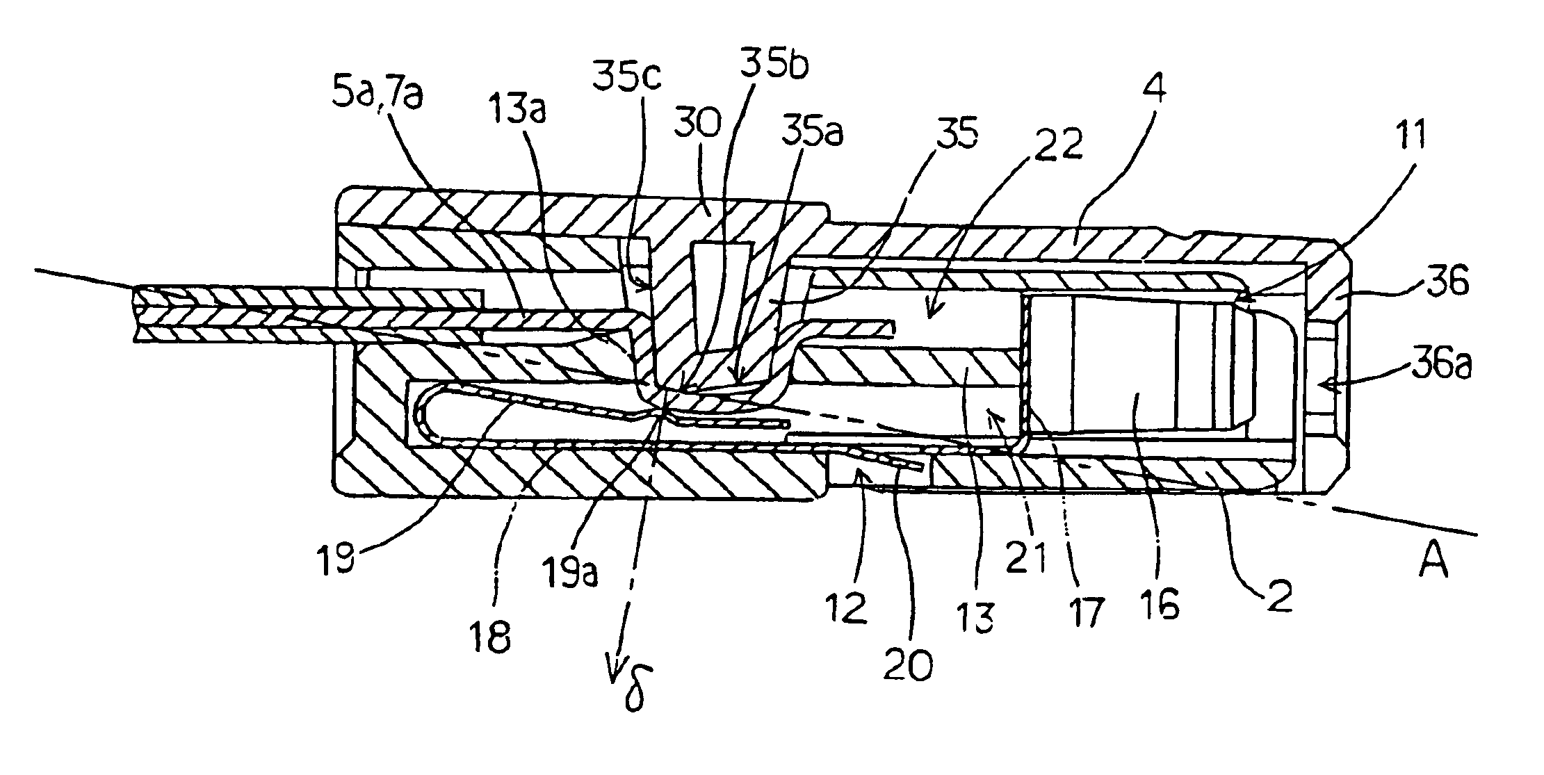
The plug 1 is rotatably mounted within the housing 4 of the casing 2 The plug 1, for example the component for connecting the amplifier to the speaker for a hi-fi equipment, is removably inserted into a rectangular recessed portion 51 of a machine side socket 40. Therefore, the rotation of the housing 4 to cover the casing 2 will correspond to the sectional configuration of the recessed portion 51.
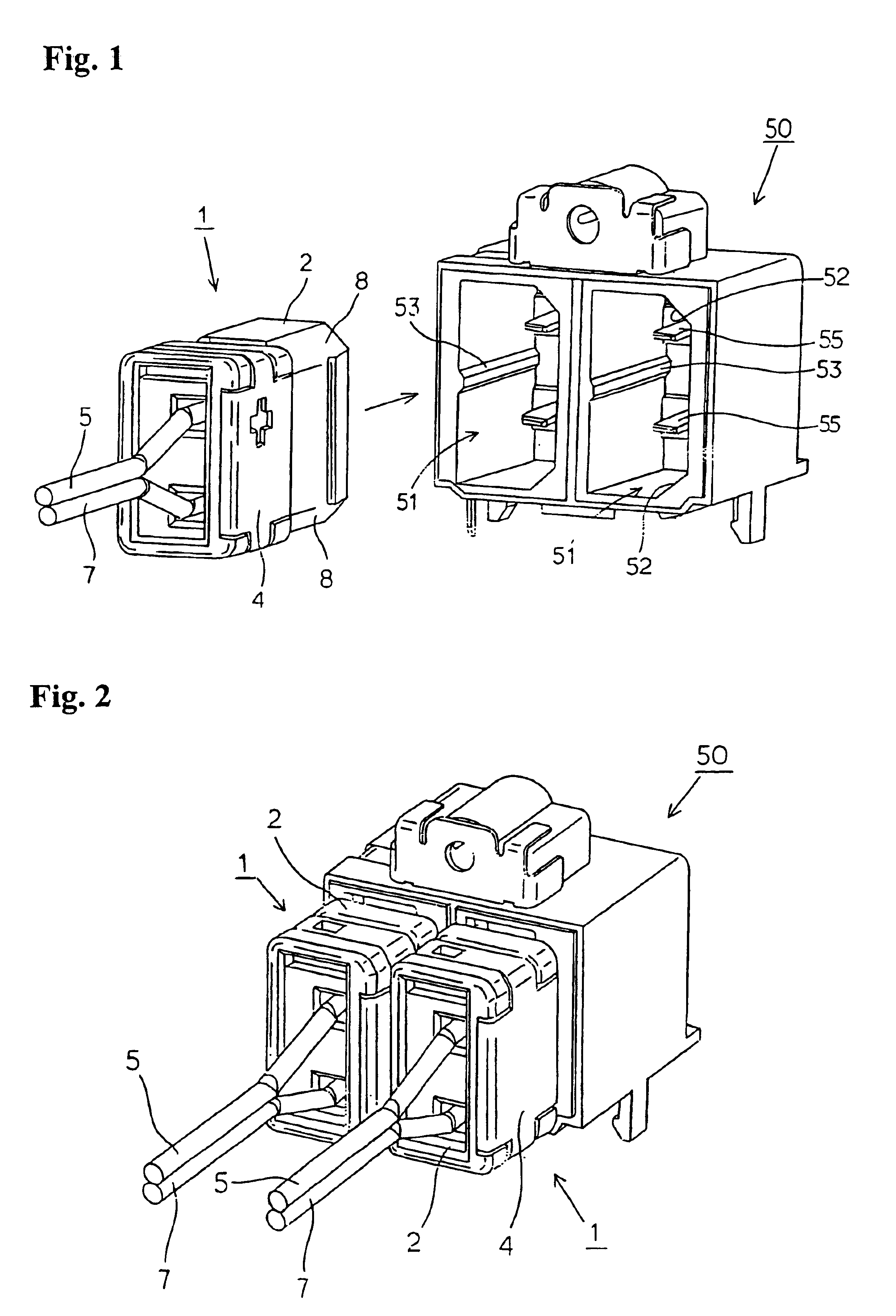
In this embodiment, a pair of recessed portions 51, 51 are juxtaposed in the socket 50 in a stereo mode configuration, as shown in FIG. 2. The recessed portions 51, 51 are adapted to receive corresponding plugs 1, 1. In FIG. 1, numeral 55 is designated for the machine side terminals mounted within the recessed portions 51. Terminal 55 is resilientl...
PUM
 Abstract
Description
Claims
Application Information