Ultrasonic monitor for measuring heart rate and blood flow rate

a monitor and ultrasonic technology, applied in ultrasonic/sonic/infrasonic diagnostics, applications, tomography, etc., can solve the problems of monitors not providing continuous heart rate readings, monitors are usually fairly large, and the technology still does not offer continuous readings. to achieve the effect of reducing cost and power consumption

Inactive Publication Date: 2005-01-18
SALUTRON
View PDF24 Cites 83 Cited by
  • Summary
  • Abstract
  • Description
  • Claims
  • Application Information

AI Technical Summary

Benefits of technology

[0012]The present invention relates to an ultrasonic monitor for measuring rate values of a living subject, including heart rate and pulse rate. Due to continued advances in piezoelectric material and microelectronic technologies, an ultrasound based pulse rate monitor system can be miniaturized to reduce cost and power consumption.

Problems solved by technology

Most, if not all, of these monitors do not provide continuous heart rate readings but measure the wearer's pulse and transmit that pulse upon request.
Most users would have to stop exercising in order to get this type of measurement, which is disruptive to an exercise regimen.
However, this technology still does not offer continuous readings.
However, such monitors are usually fairly large (e.g., size of a small TV) and are connected to the patient through specific wires.
This technique requires only one crystal but the detector circuit will only work after the transmitter power is turned off.
However, for superficial blood vessels this technique requires very high speed power switching due to the short distance between source and object.
In addition, muscle movement will also generate reflections that compromise the signal-to-noise-ratio in the system.
Therefore, it is very difficult to detect heart rate this way when the living subject is in motion.
However, ultrasonic energy is prone to diffraction and attenuation at the interface of two media of different densities.
Any air gap at the interface or any air bubbles in the media will also make ultrasonic energy transfer unreliable.
Unfortunately water and aqueous gels dry up quickly in open air.
For continuous rate monitoring, the requirement to apply water or gel frequently is not acceptable.
However, this increases the complexity and cost of the transducer device and its driving electronics significantly.
The disadvantages of continuous mode over pulsed mode are higher cost and more power consumption.

Method used


Image

  • Ultrasonic monitor for measuring heart rate and blood flow rate
  • Ultrasonic monitor for measuring heart rate and blood flow rate
  • Ultrasonic monitor for measuring heart rate and blood flow rate

Examples


Embodiment Construction

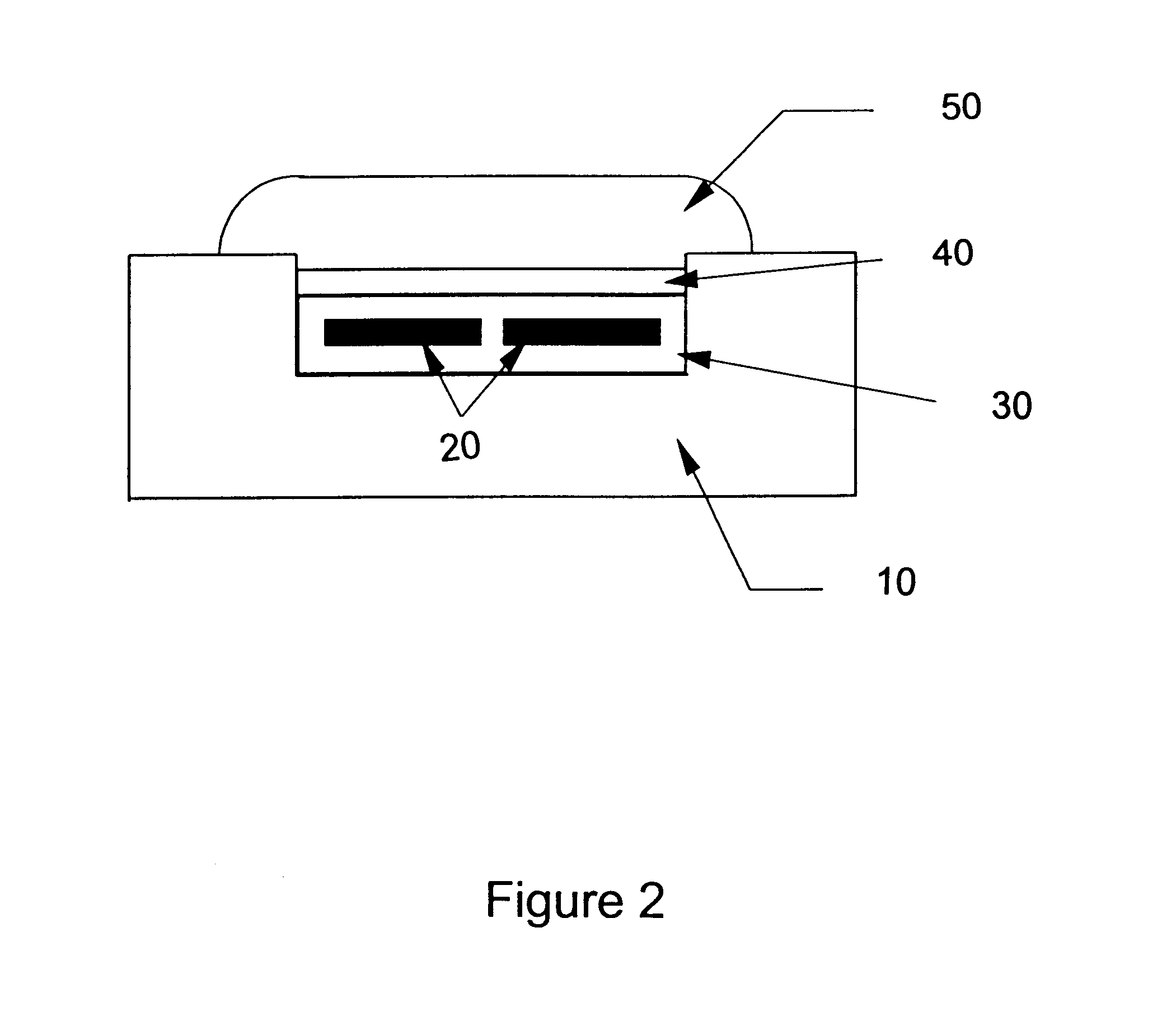
d_n">[0023]FIG. 4 depicts the block diagram of the software of this invention. The amplified Doppler signal after anti-aliasing filtering is sampled by an A / D converter in a microcontroller. The sampled data is further digitally filtered by a high pass filter or a combination of high pass and low pass filters. The output is applied with either an absolute value operator or a square operator followed by a stage of low pass filter. Finally this digitally processed data is used to determine the pulse rate.

DETAILED DESCRIPTION OF THE INVENTION

[0024]a) Definitions and General Parameters

[0025]The following definitions are set forth to illustrate and define the meaning and scope of the various terms used to describe the invention herein.

[0026]The terms “ultrasonic” and “ultrasound” are used interchangeably herein and refer to a sound wave having a frequency between about 1 MHz and about 10 MHz. An “ultrasonic transducer” (i.e., a transducing means) is a device used to introduce sonic energ...


PUM


Abstract

The invention provides an ultrasonic monitor for measuring pulse rate values in a living subject, including a module with at least one source of ultrasonic energy, a gel pad comprised of a polymer and from about 50 to about 95% by weight of an ultrasound conductive diluent, wherein the gel pad is positioned in direct contact between the module and the living subject; an ultrasonic energy detector and associated hardware and software for detecting, calculating and displaying a readout of the measured rate values.

Description

BACKGROUND OF THE INVENTION[0002]a) Field of the Invention[0003]The present invention relates to ultrasonic monitors for measuring heart and pulse rates in living subjects. Methods for measuring heart and pulse rates of living subjects through ultrasonic means are also encompassed by the instant invention.[0004]b) Description of Related Art[0005]Measuring Heart and Pulse Rates[0006]Measuring heart and pulse rates in living subjects has been accomplished by various means. The pulse rate is commonly measured by lightly touching one's fingers over an artery and counting the rate of pulsation. The heart rate is usually measured by a sensing device using electrodes that monitor the electrical activity of the heart (e.g., contact monitors) based on electrocardiograms (EKG OR ECG). Measuring rate values is a useful tool in individualizing and optimizing exercise regimens. Individuals who want to increase endurance or performance aim for certain target heart rates to maximize progression to...

Claims


Application Information

Patent Timeline
Patent Type & Authority Patents(United States)
IPC IPC(8): A61B8/02A61B8/00A61B5/024
CPCA61B5/02438A61B5/681A61B8/4281A61B8/02A61B8/4472
Inventor LO, THOMAS YING-CHINGESCORCIO, TOLENTINO
Owner SALUTRON
Why Eureka
Try Eureka