Anatomic posterior lumbar plate

a lumbar plate and anatomic technology, applied in the field of spinal surgery, can solve the problems of less effective control of vertebral motion by redundant annular fibers, less able to handle compression load, and thinner nucleus,

Inactive Publication Date: 2005-01-18
FERREE BRET A
View PDF18 Cites 53 Cited by
  • Summary
  • Abstract
  • Description
  • Claims
  • Application Information

AI Technical Summary

Benefits of technology

It is therefore an object of the present invention to provide a plate system for spinal surgery which comfortably fits a patient's anatomy.

Problems solved by technology

The nucleus becomes thinner and less able to handle compression loads.
The redundant annular fibers are less effective in controlling vertebral motion.
Disc herniation can also cause arthritis of the facet joints, which, in turn may cause back pain.
Such problems may include pain in the back or legs, nerve injury, risk of future nerve injury, or spinal deformity.
This device is difficult to place, and over-penetration of the screws can result in damage to the spinal cord.
Problems have resulted from over rigid fixation and stress shielding, resulting in nonunion of the bony fusion, chronic micromotion during healing, resulting in stress fracture of the fixation device at either the screw to the plate resulting in screw backout, or inadequate fixation strength and resultant collapse of the graft and angulations of the spine.
However, this construct extends outwardly further than a plate / screw system, potentially affecting the surrounding muscle, and causing pain to the patient.
One problem that sometimes arises in the use of known plate systems is when the points on the vertebrae defined by the screws are not collinear, i.e. they do not line up in a straight line.
This creates a problem when the openings in the plate do not align with the position where the screws are to be inserted.
The plate must then be contoured intraoperatively, which is often a difficult and time consuming task.
Still another problem which arises when using spinal plates is the differences in spinal curvature depending on the location of the vertebrae to be stabilized.

Method used


Image

  • Anatomic posterior lumbar plate
  • Anatomic posterior lumbar plate
  • Anatomic posterior lumbar plate

Examples


Embodiment Construction

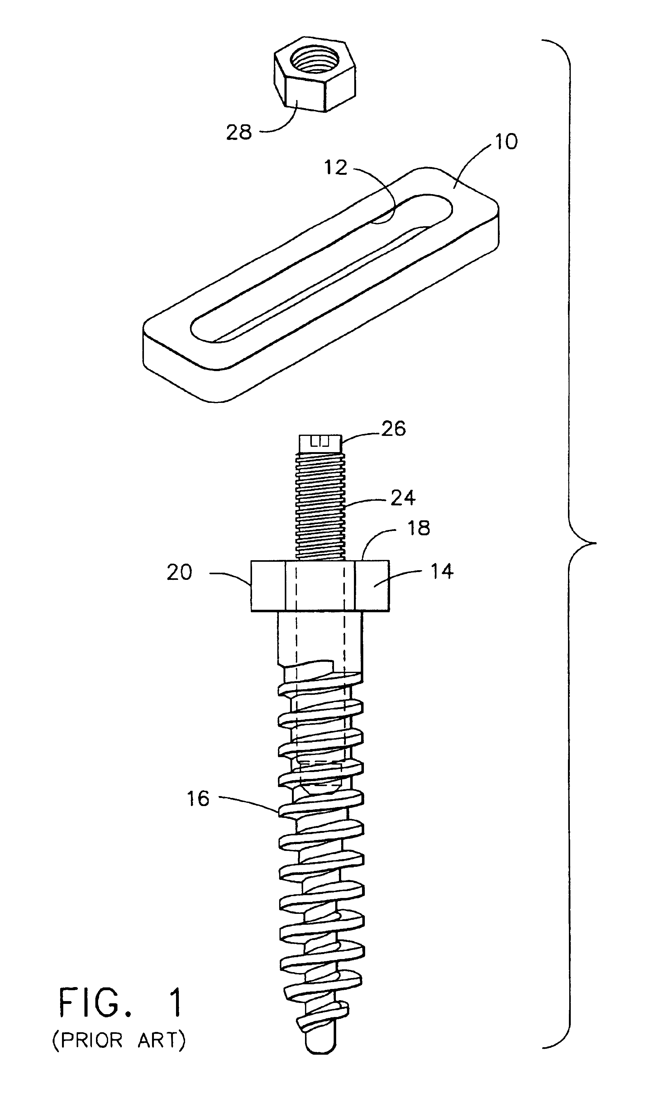
FIGS. 1 and 2 represent a typical prior art plate system currently used for spinal stabilization. Referring now to FIG. 1, there is shown a spinal plate 10. Plate 10, which is generally rectangular or elliptical in shape, contains an opening 12 in its central portion. A pedicle screw 14 is shown having a threaded shaft 16 and an upper region 18. Screw 14 contains an extended section 20 shaped to easily receive a tool for threading screw 14 into the bone. Upper region 18 is shown having a threaded section 24 and a head 26. Head 26 is of a lesser diameter than threaded section 24 such that a nut 28 can be threaded onto threaded portion 24 of inner screw 22.

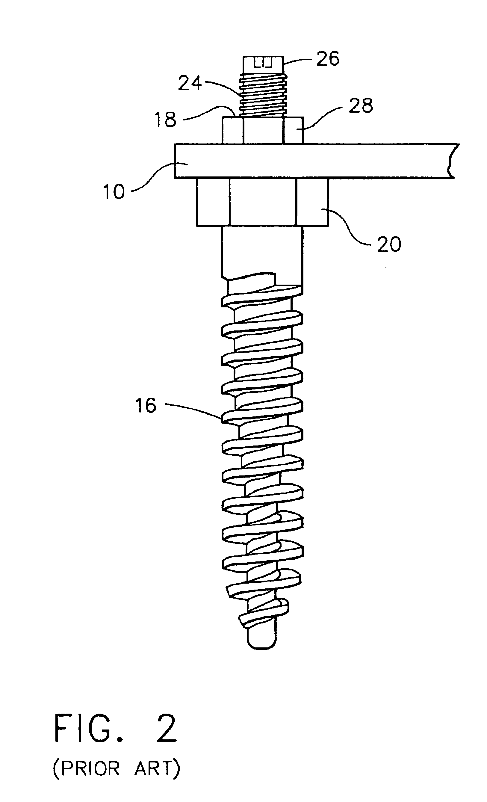
Referring now to FIG. 2, the plate system of FIG. 1 is shown in its assembled position. Plate 10 is positioned on pedicle screw 14 through opening 12 after it has been installed into the bone such that section 20 contacts the bottom side of plate 10. Nut 28 is then threaded onto threaded shaft 24 and against the upper surface of pla...


PUM


Abstract

An anatomic posterior lumbar system comprising of a thin plate and fasteners for securing the plate to vertebra or other osseous material. The plate is preferably a thin rectangular structure having an opening running lengthwise in its central portion. At least one pedicle screw having a hollow threaded interior is fastened to a vertebra, and the plate located on the screw using the opening. A washer spans the width of the plate, and accommodates an inner screw, which is threaded into the pedicle screw, and captures the head of the inner screw. Miscellaneous shapes of plates are also disclosed which are fitted to specific portions of the spine.

Description

BACKGROUND OF THE INVENTION1. Field of the InventionThis invention relates generally to devices for use in spinal surgery, and, in particular, to an anatomic posterior lumbar plate which is implantable within a patient for stabilization of the spine.2. Description of the Related ArtEighty-five percent of the population will experience low back pain at some point. Fortunately, the majority of people recover from their back pain with a combination of benign neglect, rest, exercise, medication, physical therapy, or chiropractic care. A small percent of the population will suffer chronic low back pain. The cost of treatment of patients with spinal disorders plus the patient's lost productivity is estimated at 25 to 100 billion dollars annually.Seven cervical (neck), 12 thoracic, and 5 lumbar (low back) vertebrae form the normal human spine. Intervertebral discs reside between adjacent vertebra with two exceptions. First, the articulation between the first two cervical vertebrae does not...

Claims


Application Information

Patent Timeline
Patent Type & Authority Patents(United States)
IPC IPC(8): A61B17/70A61B17/86A61B17/68A61B17/80
CPCA61B17/7059A61B17/8695A61B17/8665A61B17/8047Y10S606/901Y10S606/907Y10S606/909Y10S606/90
Inventor FERREE, BRET A.
Owner FERREE BRET A
Why Eureka
Try Eureka