Self-renewing air filter

a self-renewing, air filter technology, applied in the direction of filtration separation, auxillary pretreatment, separation process, etc., to achieve the effect of less resistance, greater stress, and a larger amount of clean air filter

Inactive Publication Date: 2005-01-18
MLS INNOVATIONS
View PDF9 Cites 31 Cited by
  • Summary
  • Abstract
  • Description
  • Claims
  • Application Information

AI Technical Summary

Benefits of technology

When a sheet of filter material is stretched between rolls within an air passageway, it represents resistance to the flow of the air. A clean air filter will present less resistance than a dirty filter. Resistance to flow reveals itself as normal and shearing stresses. A dirtier filter will present greater stresses than a cleaner filter. Because of the stresses, there is a resultant force on the filter material, causing it to “billow” in the direction of the air flow. The initial movement occurring when air flow begins is used, in the present invention, to advance the “gathering roll,” exposing some clean filter to the flow. More resistance, due to a dirtier air filter, results in greater advancement, which exposes a larger amount of clean air filter off the dispensing roll.
There is adequate swing available to the lever arm bracket so that it can advance the gathering roll's drive gear multiple gear teeth if the resistance to flow is sufficiently great (i.e. if the filter is sufficiently dirty). If the filter is not particularly dirty, it may not advance at all, or perhaps only one gear tooth. In this way, this invention is self-regulating. The greater the need for clean filter material, the greater amount of clean filter material is exposed with each cycle.

Problems solved by technology

Because of the stresses, there is a resultant force on the filter material, causing it to “billow” in the direction of the air flow.

Method used


Image

  • Self-renewing air filter
  • Self-renewing air filter
  • Self-renewing air filter

Examples


Embodiment Construction

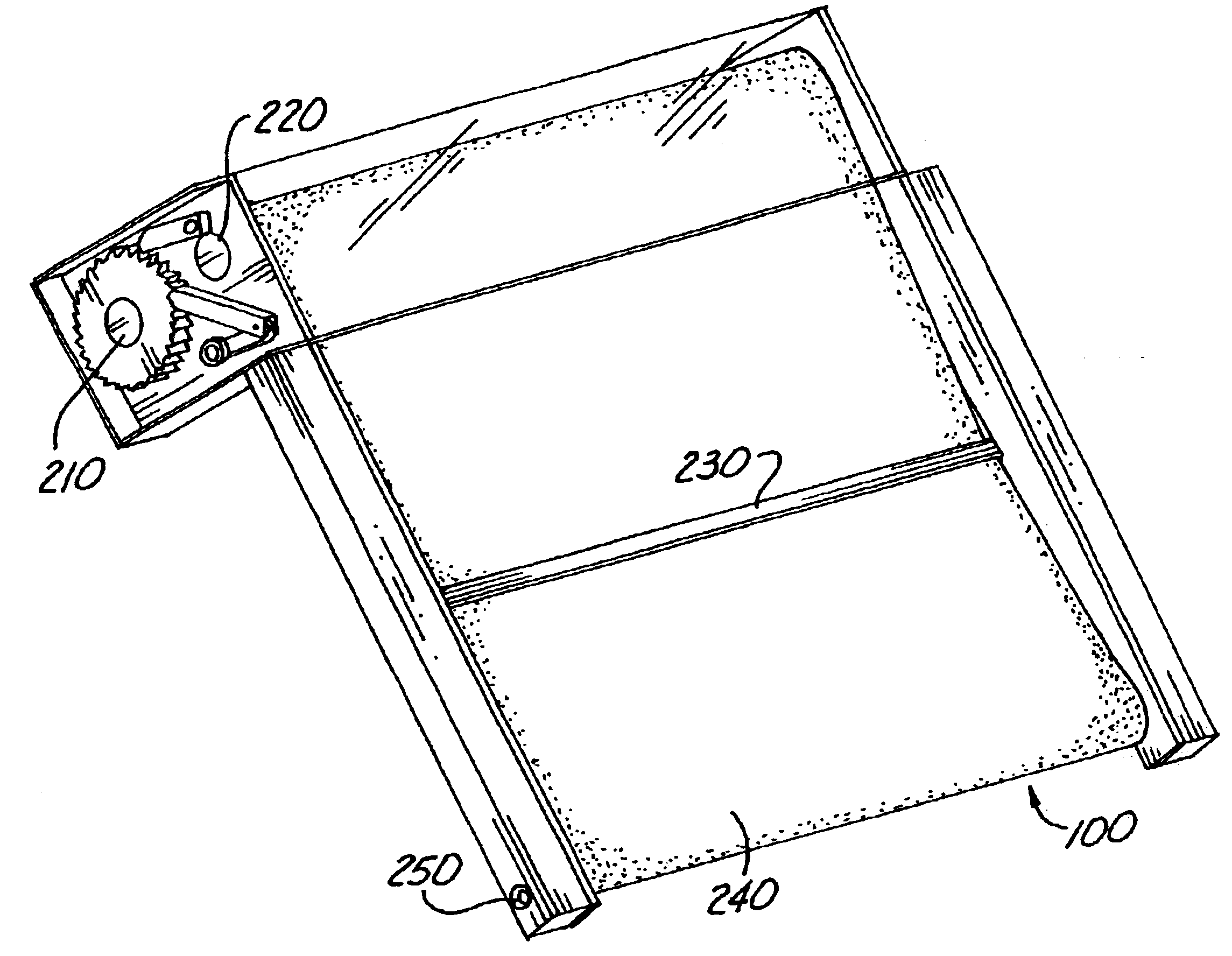
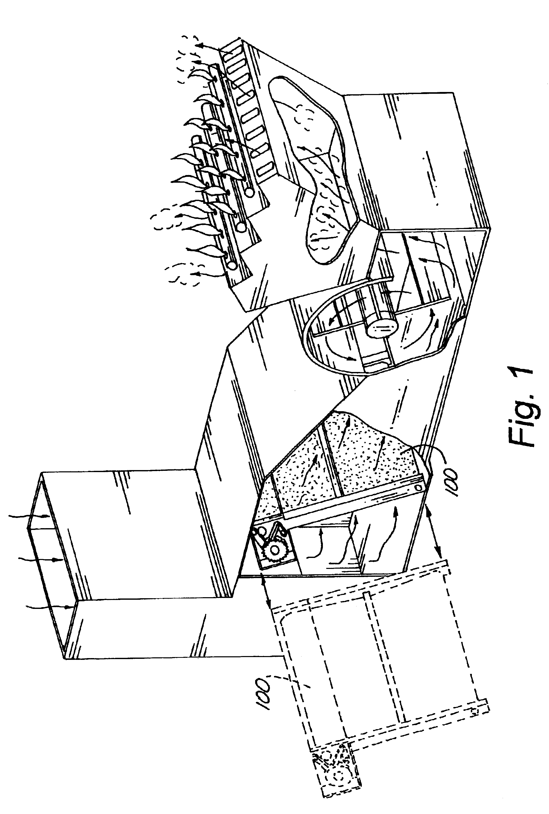
A self-renewing air filter assembly 100 is shown in place inside a furnace duct in FIG. 1. The same self-renewing air filter assembly 100 is shown in dashed lines to indicate how it is installed into the duct. According to the preferred embodiment, the self-renewing filter assembly 100 is oriented at an angle compared to the vertical, however, this invention is not limited to that orientation.

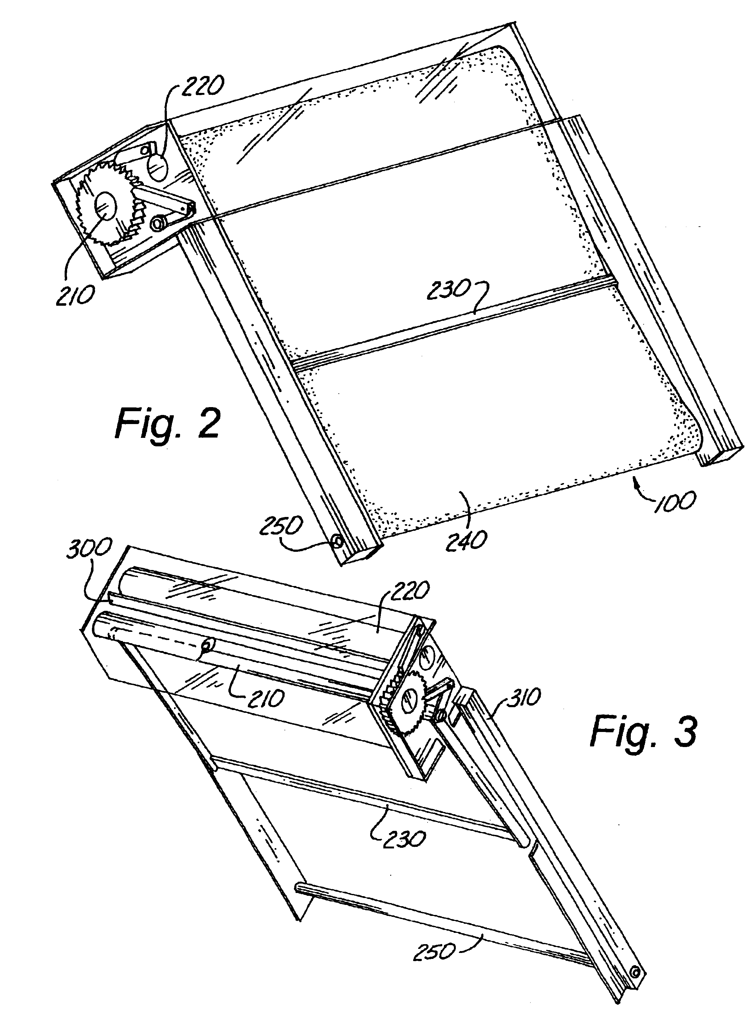
Another view of the self-renewing air filter assembly 100 is shown in FIG. 2. The end of the gathering roll 210 and the end of the dispensing roll 220 can be seen. The lever arm bracket 230 pivots on the gathering roll and lies on the sheet-type filtering material 240. In the preferred embodiment for HVAC applications, the gathering roll 210 and dispensing roll 220 are at one end of the self-renewing air filter assembly 100, and the filter sheet 240 wraps around a bar 250 (the end of which can be seen in FIG. 2) at the other end of the self-renewing air filter assembly 100. For automotive appli...


PUM

PropertyMeasurementUnit
forceaaaaaaaaaa
movementaaaaaaaaaa
rotationaaaaaaaaaa

Abstract

The replacement of filters for Heating, Ventilating, and Air Conditioning (HVAC) is often time-consuming and labor-intensive. Organizations having responsibility for many apartment or dormitory units can spend a significant fraction of their man-hours replacing such filters. A novel approach to reducing the labor for this task is to attach one end of sheet-type filtering material to a dispensing roll, and the other end to a gathering roll; both rolls being affixed to a frame. The assembly is installed into an air duct and the filtering material allowed to blouse, somewhat. The flow of air is intermittent in typical HVAC systems, so when the air begins to flow, the filtering material is forced, due to its resistance to flow, in the direction of the flow. This energy—a force applied through a distance—is utilized by a lever arm bracket to advance the gathering roll. In this fashion, new material leaves the dispensing roll and is exposed to the air, while the dirty filter sheet accumulates on the gathering roll. The process is self-regulating because dirty filter material will present a greater resistance to flow and will, therefore, travel through a greater distance, advancing the gathering roll more.

Description

BACKGROUND OF THE INVENTION1. Field of the InventionThe present invention relates generally to air filtration. More particularly the present invention relates to a method and apparatus for an air filter that renews itself automatically, greatly reducing the time required for replacement.2. Background ArtFilters for furnaces and air conditioning equipment are typically rigid, framed units (for residential and commercial applications) or in the form of sheets that are stretched between rolls on either side of an air duct (for commercial and industrial applications). Rigid, framed filters are time consuming to replace. As for the sheet-type filters used in commercial and industrial applications, one of the rolls (on one side of the air duct) is drivable. It may use a stepper motor or may be hand-cranked. In the former case, there is significant expense associated with an automatically controlled filter. In the latter, although some manpower is conserved, the filters still need regular ...

Claims


Application Information

Patent Timeline
Patent Type & Authority Patents(United States)
IPC IPC(8): B01D46/18B01D46/22B60H3/06
CPCB60H3/06B01D46/22
Inventor SCHUMACHER, JERRY H.
Owner MLS INNOVATIONS
Why Eureka
Try Eureka