
Terahertz transceivers and methods for emission and detection of terahertz pulses using such transceivers

a transceiver and terahertz technology, applied in the field of transceivers, can solve the problems of not being able to provide an acceptable signal-to-noise ratio, not known or used before, and achieve the effect of reducing noise in the first signal and reducing nois

Inactive Publication Date: 2005-01-18
RENESSELAER POLYTECHNIC INST
View PDF30 Cites 44 Cited by
  • Summary
  • Abstract
  • Description
  • Claims
  • Application Information

AI Technical Summary

Benefits of technology

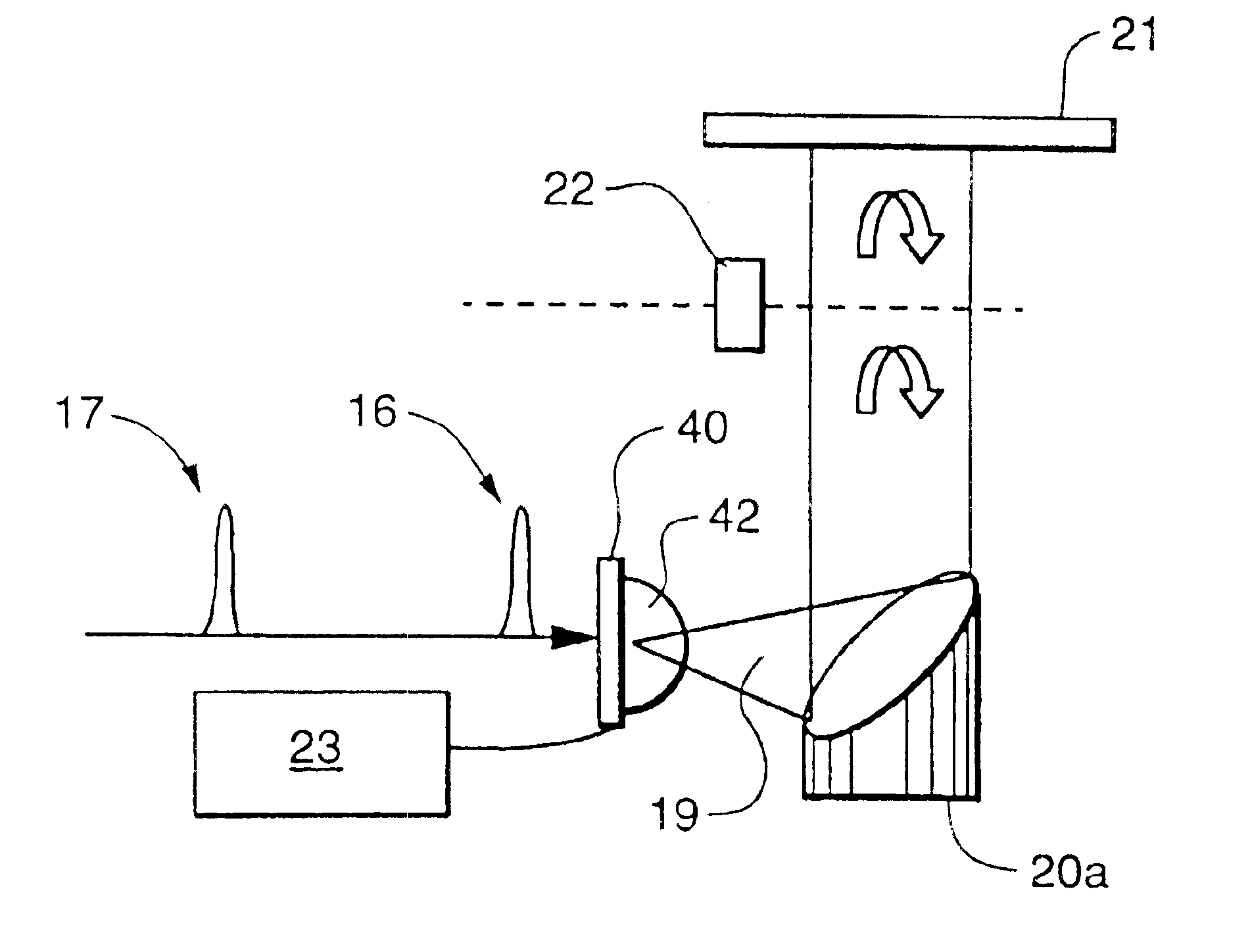
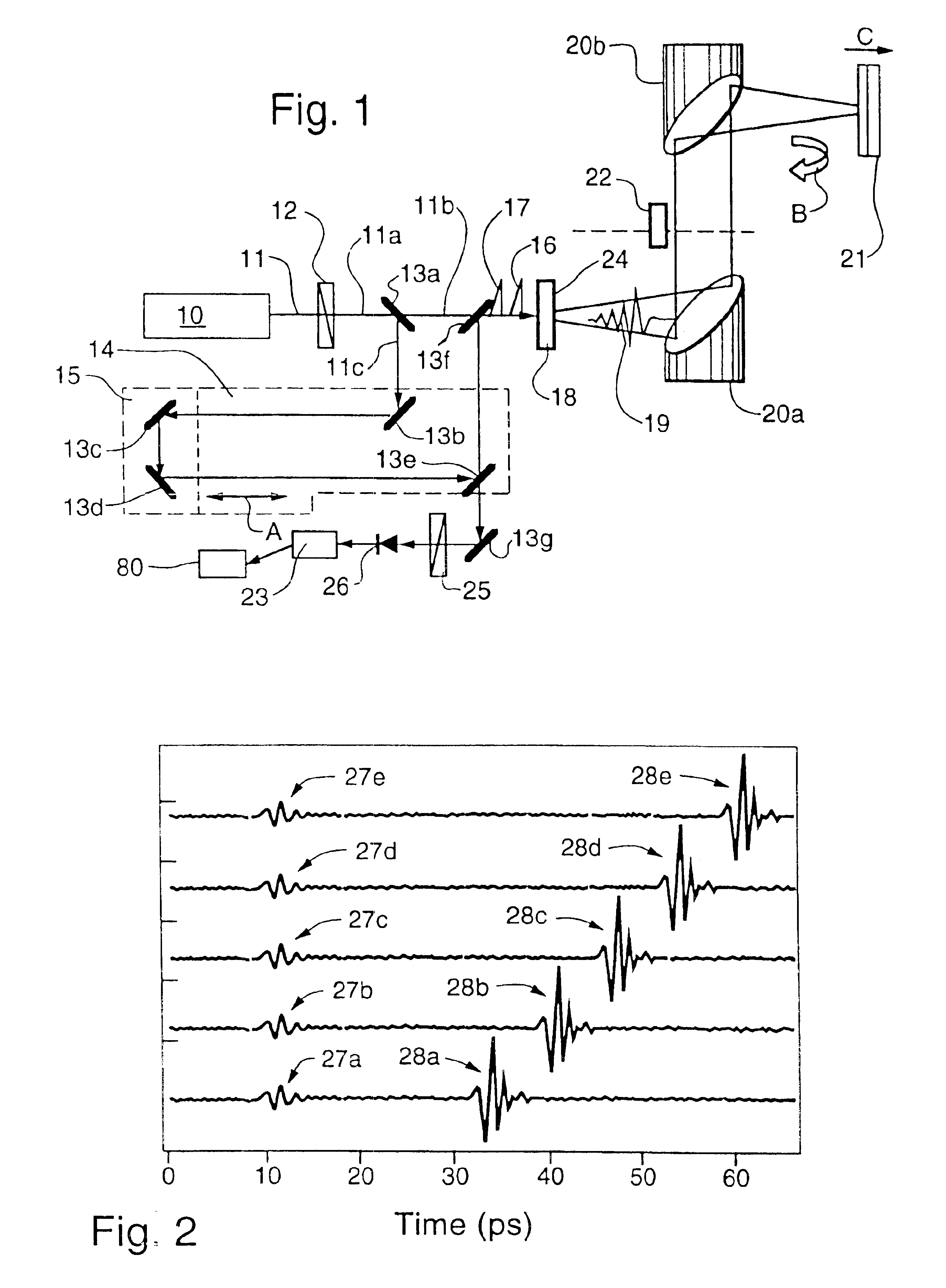
[0008]In one embodiment, the system further comprises an optical source and related optics for providing a plurality of pump pulses to excite the transceiver to emit a corresponding plurality of terahertz output pulses and a plurality of probe pulses. A chopper modulates the terahertz output pulses at a first frequency. An object is illuminated by the modulated terahertz output pulses and reflects the plurality of modulated terahertz output pulses. The probe pulses are timed to illuminate the transceiver simultaneously with a corresponding plurality of reflected terahertz pulses. A lock-in amplifier, having its reference input connected to the clock output of the chopper, receives a plurality of electrical signals carrying information proportional to the corresponding reflected terahertz pulses detected by the transceiver. The use of the synchronized chopper and lock-in amplifier allows the lock-in amplifier to reduce noise in the signals.
[0011]If the transceiver device is an electro-optic crystal, the terahertz pulse modulates the probe pulse in the electro-optic crystal and the electro-optic crystal reflects the modulated probe pulse from a back surface of the electro-optic crystal. The first signal comprises the reflected, modulated probe pulse. In such a case, the method further comprises detecting the reflected, modulated probe pulse with a photodetector; converting the information to a second signal; and reducing noise in the second signal with a lock-in amplifier to produce a third, noise-reduced signal.
[0012]If the transceiver device is a photoconductive antenna, the method may include creating through the terahertz pulse and the probe pulse a current in the antenna comprising the first signal. The method further includes reducing noise in the first signal with a lock-in amplifier to produce a second, noise-reduced signal.

Problems solved by technology

Despite advantages to be gained by using a single device as both a transmitter and a receiver (a “transceiver”), terahertz transceivers have not previously been known or used in the art, primarily because of perceived technical hurdles and inherent complexity, such as the difficulty of providing an acceptable signal-to-noise ratio.

Method used


Image

  • Terahertz transceivers and methods for emission and detection of terahertz pulses using such transceivers
  • Terahertz transceivers and methods for emission and detection of terahertz pulses using such transceivers
  • Terahertz transceivers and methods for emission and detection of terahertz pulses using such transceivers

Examples


Embodiment Construction

b class="d_n">[0025]FIG. 10A is an image of an American quarter dollar generated using an exemplary embodiment of the present invention, where the gray level represents the timing of the peak amplitude;

[0026]FIG. 10B is an image of a British fifty pence piece generated using an exemplary embodiment of the present invention, where the gray level represents the timing of the peak amplitude;

[0027]FIG. 11A is an image of an American quarter dollar generated using an exemplary embodiment of the present invention, where the gray level represents the peak amplitude within a certain timing window;

[0028]FIG. 11B is an image of a British fifty pence piece generated using an exemplary embodiment of the present invention, where the gray level represents the peak amplitude within a certain timing window; and

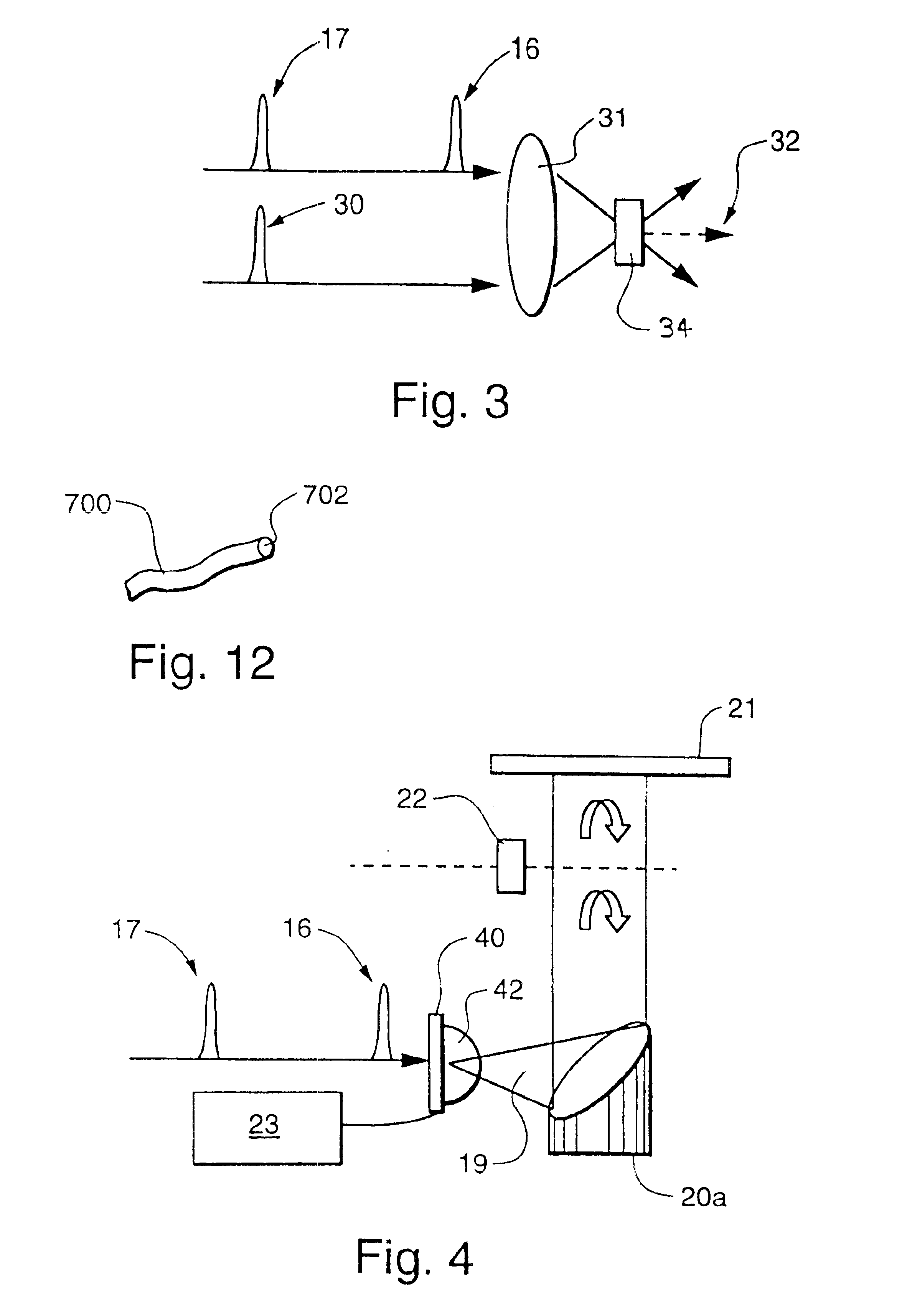
[0029]FIG. 12 illustrates an exemplary optical fiber THz transceiver.

DETAILED DESCRIPTION OF INVENTION

[0030]Unlike the conventional setup in which the THz transmitter and receiver are spatial...


PUM


Abstract

A system for emitting and detecting terahertz frequency electromagnetic pulses. The system comprises a single transceiver device, which may be an electro-optic crystal or photoconductive antenna, for both emitting and detecting the pulses. A related method comprises using a single transceiver device to both emit and detect electromagnetic terahertz frequency pulses. The transceiver device is excited by a pump pulse to emit a terahertz output pulse, which is modulated with a chopper. An object reflects the terahertz pulse and the reflected pulse is detected in the transceiver using a probe pulse. A lock-in amplifier set to the same frequency of the chopper is used to reduce noise in the signal detected by the transceiver. An image of the object may be created using the intensity or the timing of the peak amplitude of the terahertz pulses reflected from the object.

Description

CROSS-REFERENCE TO RELATED APPLICATIONS[0002]This application claims priority based upon U.S. Provisional Patent Application Ser. No. 60 / 195,554, filed on Apr. 6, 2000, and U.S. Provisional Patent Application Ser. No. 60 / 195,708, filed on Apr. 7, 2000, both of which are incorporated by reference.TECHNICAL FIELD[0003]The present invention relates generally to the emission and detection of electromagnetic pulses and, more specifically, to transceivers for use in the terahertz (THz) frequency range.BACKGROUND OF THE INVENTION[0004]Electro-optic crystals and photoconductive dipole antennas have been widely used in terahertz (THz) time-domain spectroscopy and related imaging applications. For example, U.S. Pat. No. 5,952,818, issued to Zhang et al., discloses an electro-optical sensing apparatus and method for characterizing free-space electromagnetic radiation suitable for real-time, two-dimensional, far-infrared imaging applications. Pulsed terahertz electromagnetic radiation illuminat...

Claims


Application Information

Patent Timeline
IPC IPC(8): G01N21/31G01N21/35G01J11/00G01N21/17
CPCG01N21/3581G01J11/00
Inventor ZHANG, XI-CHENGTANI, MASAHIKOJIANG, ZHIPINGCHEN, QIN
Owner RENESSELAER POLYTECHNIC INST
Learn More