Optical isolator apparatus and methods

a technology of optical isolators and isolators, which is applied in the direction of generators/motors, instruments, optical elements, etc., can solve the problems of small channel separation and difficult to achieve goals

Inactive Publication Date: 2005-01-18
INTEL CORP
View PDF96 Cites 39 Cited by
  • Summary
  • Abstract
  • Description
  • Claims
  • Application Information

AI Technical Summary

Problems solved by technology

Greater bandwidth requirements will likely result in smaller channel separation in the future.
These goals have been difficult to ac...

Method used


Image

  • Optical isolator apparatus and methods
  • Optical isolator apparatus and methods
  • Optical isolator apparatus and methods

Examples


Embodiment Construction

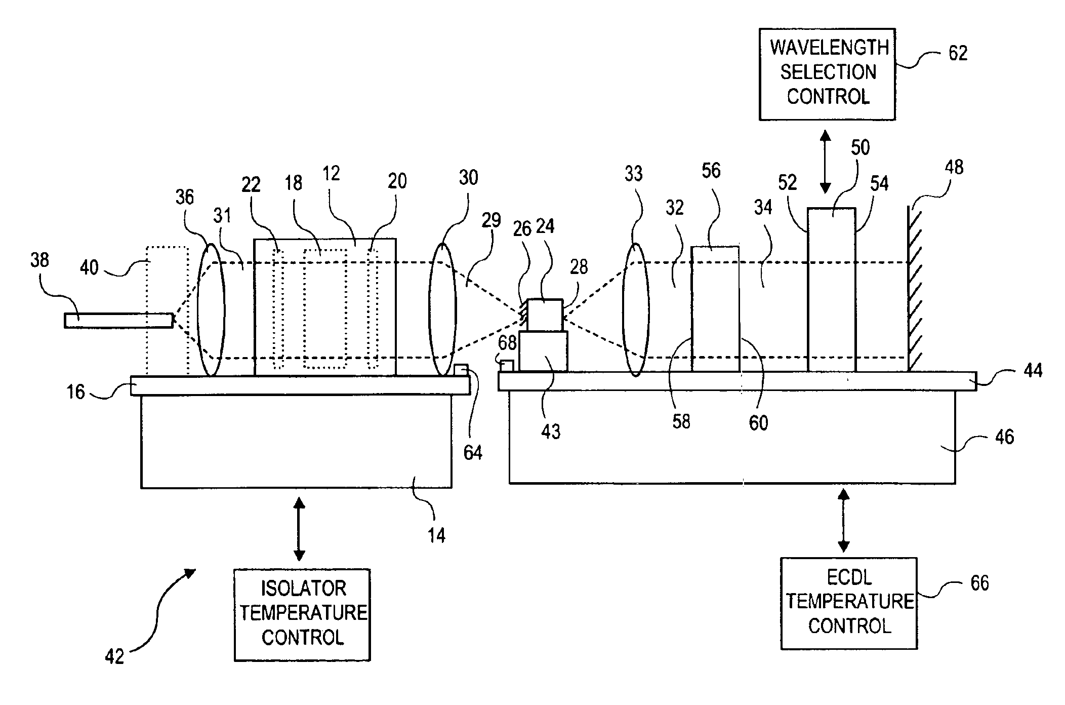
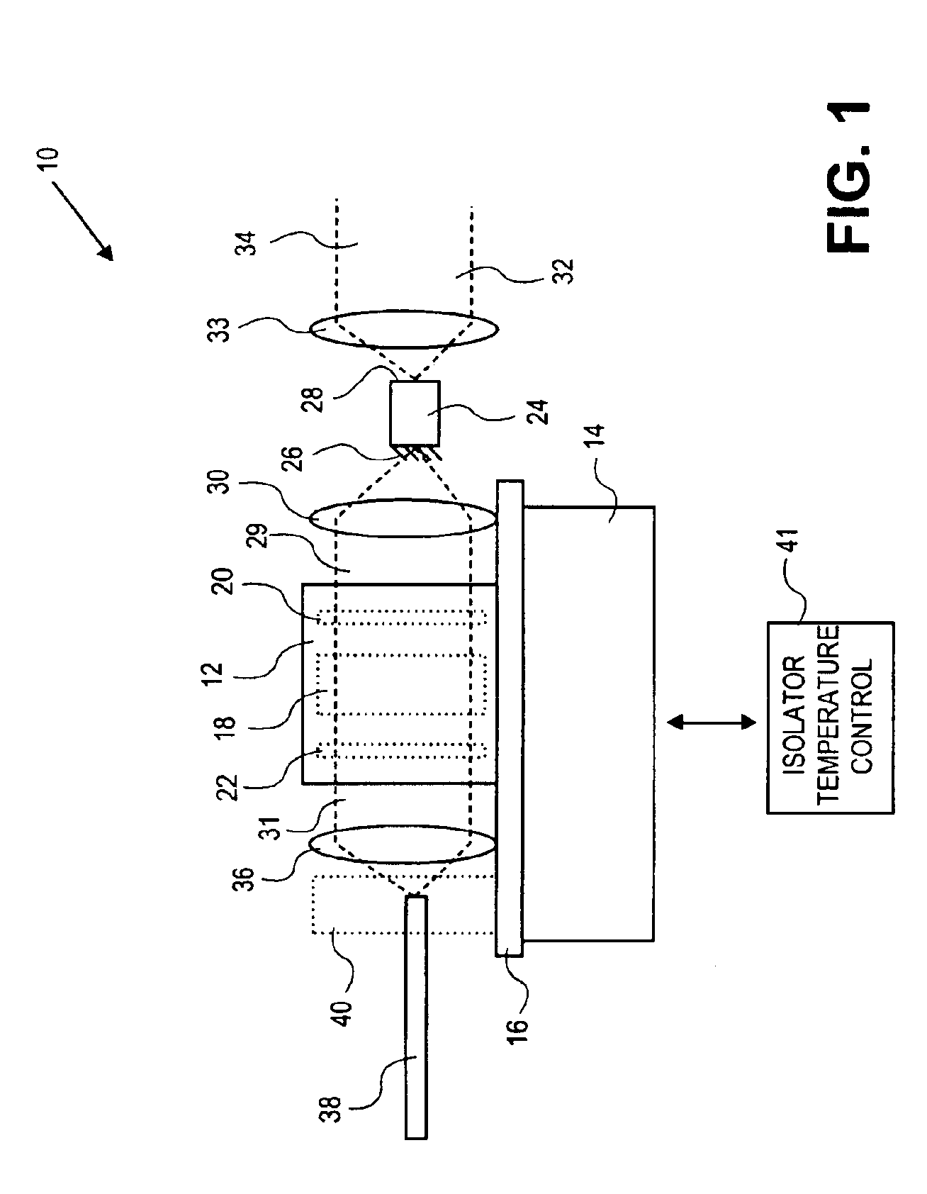
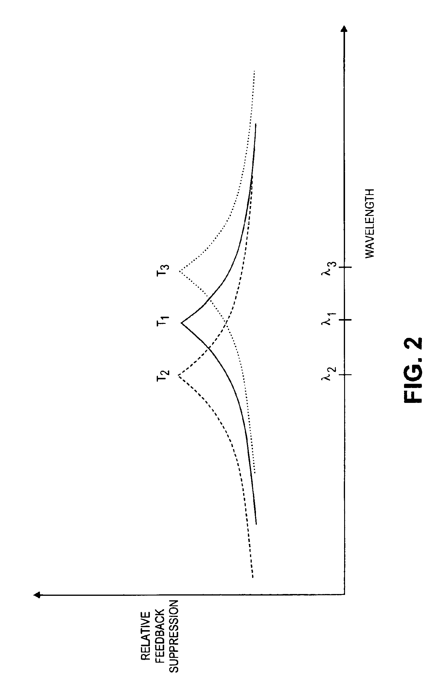
The invention provides methods and apparatus for optimizing feedback suppression of optical isolators when used with variable wavelength light sources. The methods of the invention comprise, in general terms, positioning an optical isolator in a light beam, and adjusting feedback suppression by the optical isolator according to wavelength of the light beam. The methods may further comprise adjusting wavelength of the light beam, and emitting the light beam by a gain medium.

In certain embodiments, the adjusting the feedback suppression comprises adjusting temperature of the optical isolator. The adjusting temperature of the optical isolator may comprise adjusting temperature of a non-reciprocal rotator associated with the optical isolator. Adjusting temperature of the optical isolator may comprise coupling the optical isolator to a thermal control element, thermally controlling the optical isolator with the thermal control element.

The invention also provides methods of laser operatio...


PUM


Abstract

Methods and apparatus for optimizing feedback suppression of optical isolators when used with variable wavelength light sources. The methods comprise positioning an optical isolator in a light beam, and adjusting feedback suppression by the optical isolator according to wavelength of the light beam. Adjusting the feedback suppression may comprise adjusting temperature of the optical isolator or a non-reciprocal rotator associated with the isolator.

Description

BACKGROUND OF THE INVENTIONThere is an increasing demand for tunable lasers for test and measurement uses, wavelength characterization of optical components, fiberoptic networks and other applications. In dense wavelength division multiplexing (DWDM) fiberoptic systems, multiple separate data streams propagate concurrently in a single optical fiber, with each data stream created by the modulated output of a laser at a specific channel frequency or wavelength. Presently, channel separations of approximately 0.4 nanometers in wavelength, or about 50 GHz are achievable, which allows up to 128 channels to be carried by a single fiber within the bandwidth range of currently available fibers and fiber amplifiers. Greater bandwidth requirements will likely result in smaller channel separation in the future.DWDM systems have largely been based on distributed feedback (DFB) lasers operating with a reference etalon associated in a feedback control loop, with the reference etalon defining the ...

Claims


Application Information

Patent Timeline
IPC IPC(8): G02B6/26G02F1/01
CPCG02B6/2746Y10S372/703G02F1/0147
Inventor MCDONALD, MARK
Owner INTEL CORP
Why Eureka
Try Eureka