Optical modulating device

Inactive Publication Date: 2006-02-02
NIPPON TELEGRAPH & TELEPHONE CORP
View PDF2 Cites 33 Cited by
  • Summary
  • Abstract
  • Description
  • Claims
  • Application Information

AI Technical Summary

Benefits of technology

[0018] The present invention is implemented to solve the foregoing problems. Therefore it is an object of the present invention to provide an economical optical modulation apparatus that can reduce the effect of the reflected light rays and achieve the stable amplifying function by the device specification design and device configuration considering the effect of the reflection passing through the optical amplifiers in the optical modulation apparatus with a configuration including optical amplifiers connected in a multi-stage fashion, or in the optical modulation apparatus including optical amplifiers as bidirectional optical amplifiers.
[0019] A first aspect of the present invention implements a stable amplifying function by reducing the effect of reflected light rays from end faces of a bidirectional optical amplifier by imposing a numerical limitation on the relationship between the gain of the bidirectional optical amplifier and the loss of the optical modu

Problems solved by technology

To implement a WDM signal transmission system using the multi-wavelength light, one of the important problems is the simplification of the configuration of an optical modulation circuit and its economization. FIG. 1 shows a configuration of a conventional optical modulation circuit.
In addition, as for the system having the multi-wavelength light source and the optical modulators placed at a distance physically, the losses of fiber transmission paths linking them become nonnegligible.
When the optical amplifier with the uniform gain broadening amplifies a plurality of different signal wavelengths in the saturation region of the gain, the individual wavelengths scramble for the gain, which causes crosstalk between the channels and degrades the signal waveform.
However, a broadband, high-power light amplifier covering the entire wavelength band of the multi-wavelength light is very expensive even if used alone.
Since the refl

Method used


Image

  • Optical modulating device
  • Optical modulating device
  • Optical modulating device

Examples


first embodiment

[0039] The first embodiment in accordance with the present invention has, in a transmission-type optical modulation apparatus including semiconductor optical amplifiers (SOAs) connected in cascade, optical isolators inserted at every alternate units to reduce the effect of the reflected light, thereby implementing the stable amplifying function and cost reduction at the same time. Before describing concrete configuration examples of the present t, its principle will be explained.

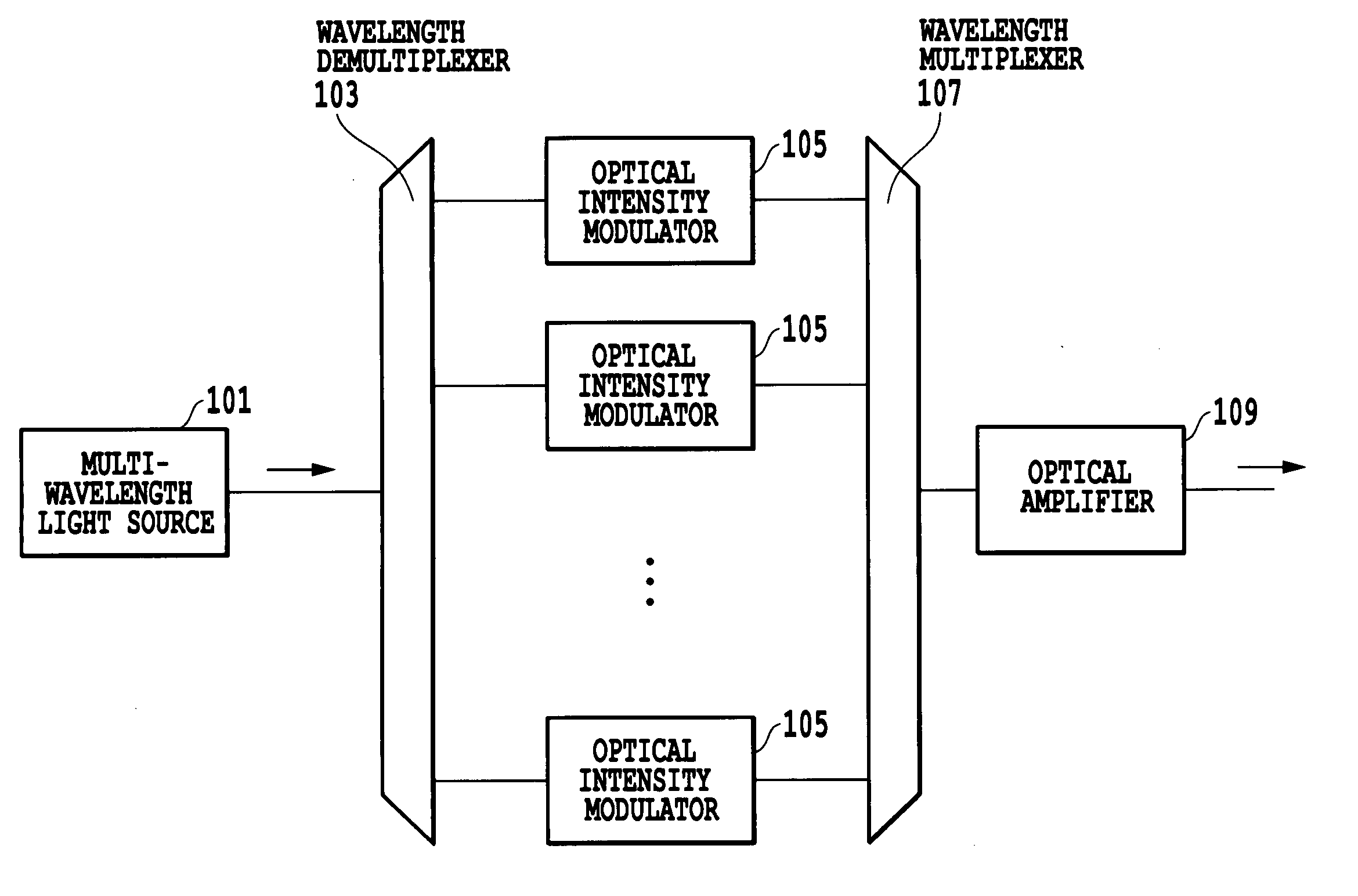
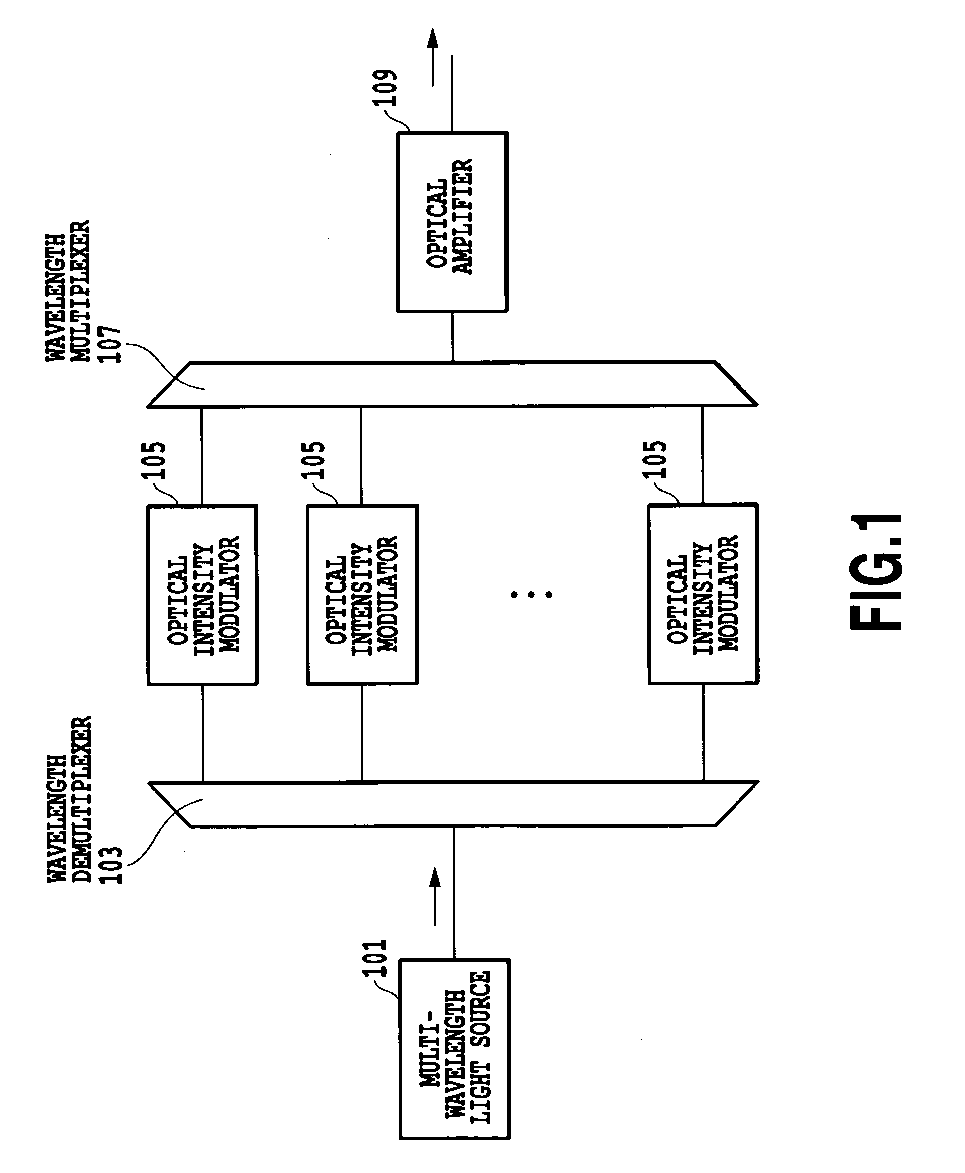
[0040]FIG. 7 is a diagram illustrating reflected light rays when a plurality of SOAs are arranged in the multistage connection. In the multistage connection, to operate it as an optical modulation apparatus, one of the SOAs must be used as an optical intensity modulator, or an external modulator must be inserted. However, to simplify the description of the reflected light rays here, the SOAs are assumed to function just as an optical amplifier.

[0041] In FIG. 7, n (>=2) semiconductor optical amplifiers (S1,...

second embodiment

[0051]FIGS. 12A-12C are diagrams each showing a configuration of the optical modulation apparatus of a second embodiment in accordance with the present invention. The present embodiment is a variation of the first embodiment, which has an optical intensity modulator M inserted between any two of three SOAs S1, S2 and S3 constituting the optical amplifier.

[0052]FIG. 12A shows a configuration having the optical intensity modulator M inserted into a section in which neither the optical isolator O1 nor O2 is inserted. Although the example is shown here which has the optical intensity modulator M inserted into the second optical path (optical connection means) x2 between the first and second SQAs S1 and S2, the optical intensity modulator M can be inserted into a fourth optical path 4 between the third SOA S3 and the output terminal. In the latter case, however, it is necessary to use an optical intensity modulator M that can handle the optical power amplified by the final stage SOA S3....

third embodiment

[0056] A third embodiment of the optical modulation apparatus in accordance with the present invention relates to a system that can achieve the stable amplifying function by reducing the effect of the reflected light rays on the end faces of the bidirectional optical amplifiers by imposing the following numerical limitation on the gain of the amplifier in the foregoing system configuration including the bidirectional optical amplifiers as shown in FIG. 4. The numerical limitation on the amplifier gain in accordance with the present invention will be described below.

[0057] As shown in FIG. 4, there are two reflected light rays from the ends of the bidirectional optical amplifier 409 or 415: first reflected light 1 travels in the same direction as the modulated light, and second reflected light 2 travels in the same direction as the continuous wave. The continuous wave undergoes the intensity modulation and becomes the modulated light. Since the reflected light 2 travels through the ...


PUM


Abstract

An optical modulation apparatus is provided which implements a stable amplifying function by reducing the effect of reflected light rays form end faces of a bidirectional optical amplifier by imposing a numerical limitation on the relationship between the gain of the bidirectional optical amplifier and the loss of the optical modulator, or by inserting a polarization rotation section in a reflection type optical modulator including the bidirectional optical amplifier or in a multi-wavelength collective optical modulation system combining the multiple optical modulators. An optical modulation apparatus is provided which implements a stable amplifying function and cost reduction by reducing the effect of reflected light rays by interposing optical isolators at every alternate SOAs in a transmission-type optical modulation apparatus including a plurality of semiconductor optical amplifiers (SOAs) connected in a multistage fashion.

Description

TECHNICAL FIELD [0001] The present invention relates to an optical modulation apparatus used for optical communication, and particularly to a constructing technique of the optical modulation apparatus constructed by combining an optical amplifier such as a semiconductor optical amplifier with an optical intensity modulator. BACKGROUND ART [0002] Conventionally, systems have been studied which apply multi-wavelength light including a plurality of optical carriers generated by an optical short-pulse laser or by amplitude modulation / phase modulation to wavelength division multiplexing (WDM) signal transmission. Such multi-wavelength light has the same spectral spacing between individual side modes so that the channels obtained by wavelength demultiplexing of the side modes have the same wavelength spacing. Accordingly, such multi-wavelength light is simpler in wavelength constellation than multi-wavelength light based on a method of preparing separate lasers for individual channels and...

Claims


Application Information

Patent Timeline
IPC IPC(8): H04B10/04H01S3/00H04B10/29G02F1/01H04B10/2507H04B10/297H04B10/516H04B10/54H04B10/61H04J14/02
CPCH04B10/2587H04J14/02H04B2210/258H04B10/2971
Inventor FUJIWARA, MASAMICHIKANI, JUNICHIAKIMOTO, KOJIIWATSUKI, KATSUMI
Owner NIPPON TELEGRAPH & TELEPHONE CORP
Why Eureka
Try Eureka