
Poled fiber, a method of fabricating the poled fiber, and a dispersion compensator

a technology of poled fiber and compensator, which is applied in the field of poled fiber, can solve the problems of imposing the character of second-order nonlinearity on the fiber, inability to achieve the desired effect, and the distance between the fiber core and the electrode is too close, so as to achieve the effect of compensating for the chromatic dispersion and high electro-optic coefficien

Inactive Publication Date: 2005-01-18
ELECTRONICS & TELECOMM RES INST
View PDF8 Cites 2 Cited by
  • Summary
  • Abstract
  • Description
  • Claims
  • Application Information

AI Technical Summary

Benefits of technology

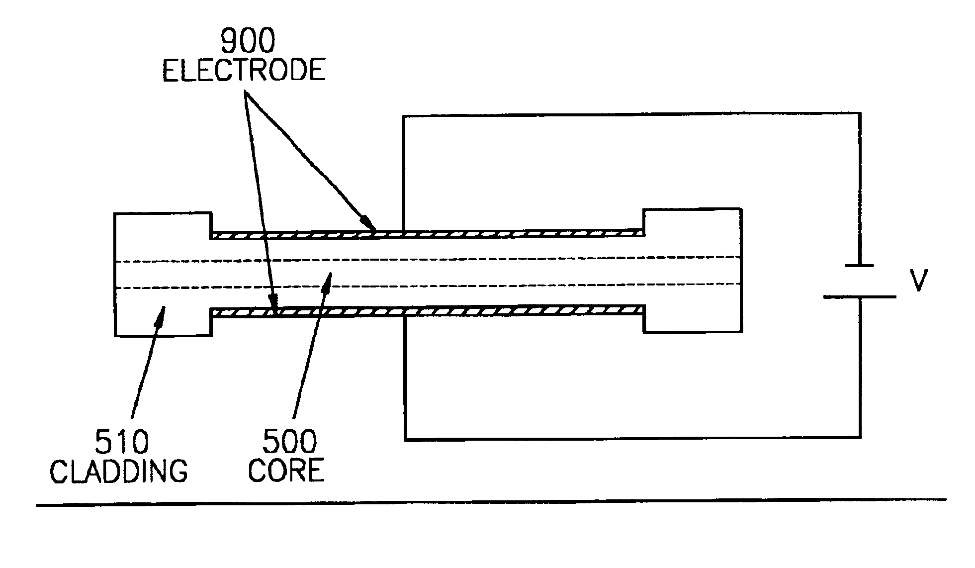
It is the object of the present invention to provide a poled fiber of almost no splicing loss with other typical fibers due to easy splicing, a method of fabricating the poled fiber with a high electro-optic coefficient induced by controlling the distance between electrodes around the core in use of a typical fiber instead of a special fiber, and a dispersion compensator capable of effectively compensating for the chromatic dispersion of a single mode fiber even if the wavelength of pump light is around ½ of signal light.

Problems solved by technology

However, if a static electrical field is applied to the fiber at a high temperature, the characteristic of the second-order nonlinearity is imposed to the fiber due to the poling effect breaking the centro-symmetry.
However, it is not desirable that the distance between the fiber core and the electrode is too close because of large loss of light propagating through the core in the poled fiber.
But these techniques are very picky to satisfy the condition and the wavelength range allowed by the phase matching is extremely limited.
However, no concrete technique capable of forming periodic poling has been developed yet.
However, the D-shaped fibers formed by mechanical polishing leads to a degradation in precision, and the processes of evaporation of a fine electrode pattern onto the flat sides of the fiber is more or less complicate.
Also the distance between electrodes is relatively long and the wire electrodes are not reusable.
Meanwhile, a single mode fiber, which is a transmission path in an optical communication system, has limited transmission capacity and distance because of chromatic dispersion.
However, the chromatic dispersion compensator disclosed in Korean Patent Publication No. 2001-11093 can only be used in case of the signal and the pump lights with similar wavelengths, and cannot be practically used in case the wavelength of pump light is ½ of signal light.

Method used


Image

  • Poled fiber, a method of fabricating the poled fiber, and a dispersion compensator
  • Poled fiber, a method of fabricating the poled fiber, and a dispersion compensator
  • Poled fiber, a method of fabricating the poled fiber, and a dispersion compensator

Examples


Embodiment Construction

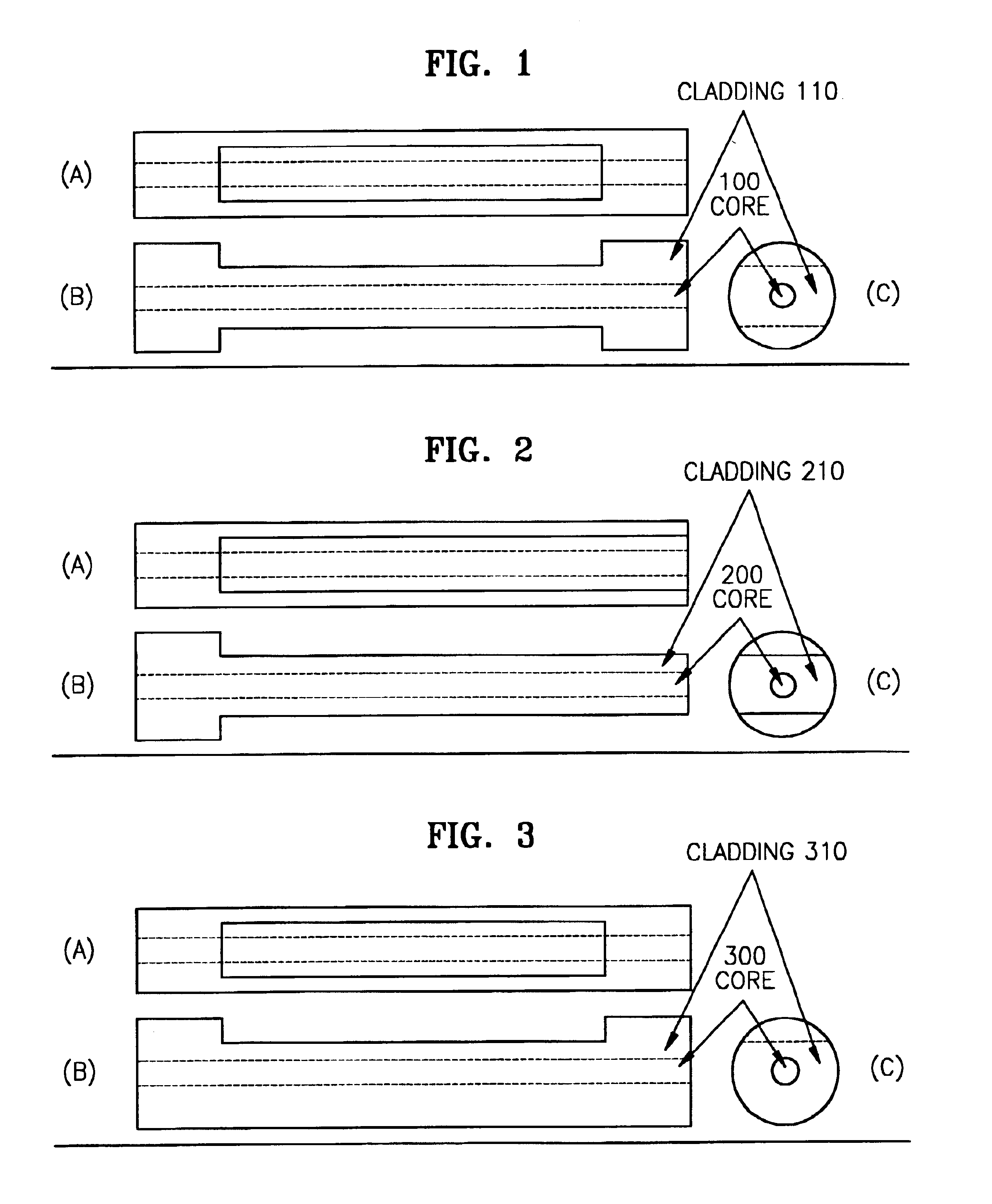
In each of FIGS. 1 through 4, (a) is a front view from the direction to which an etching material is projected so as to form a groove on the optical fibre, (b) is a side view from the direction of a grooved optical fibre, and (c) is a cross-section of an optical fibre.

Referring to FIG. 1, grooves are formed on the opposite sides along the longitudinal direction of the optical fibre while parts of both ends of the optical fibre keep the original core-cladding structure.

Referring to FIG. 2, grooves are formed on the opposite sides along the longitudinal direction of the optical fibre while only one end part of the optical fibre keeps the original core-cladding structure.

Referring to FIG. 3, a groove is formed on one side along the longitudinal direction of the optical fibre while parts of both ends of the optical fibre keep the original core-cladding structure.

Referring to FIG. 4, a groove is formed on one side along the longitudinal direction of the optical fibre while only one end p...


PUM

PropertyMeasurementUnit
dispersionaaaaaaaaaa
a wavelengthaaaaaaaaaa
difference frequencyaaaaaaaaaa

Abstract

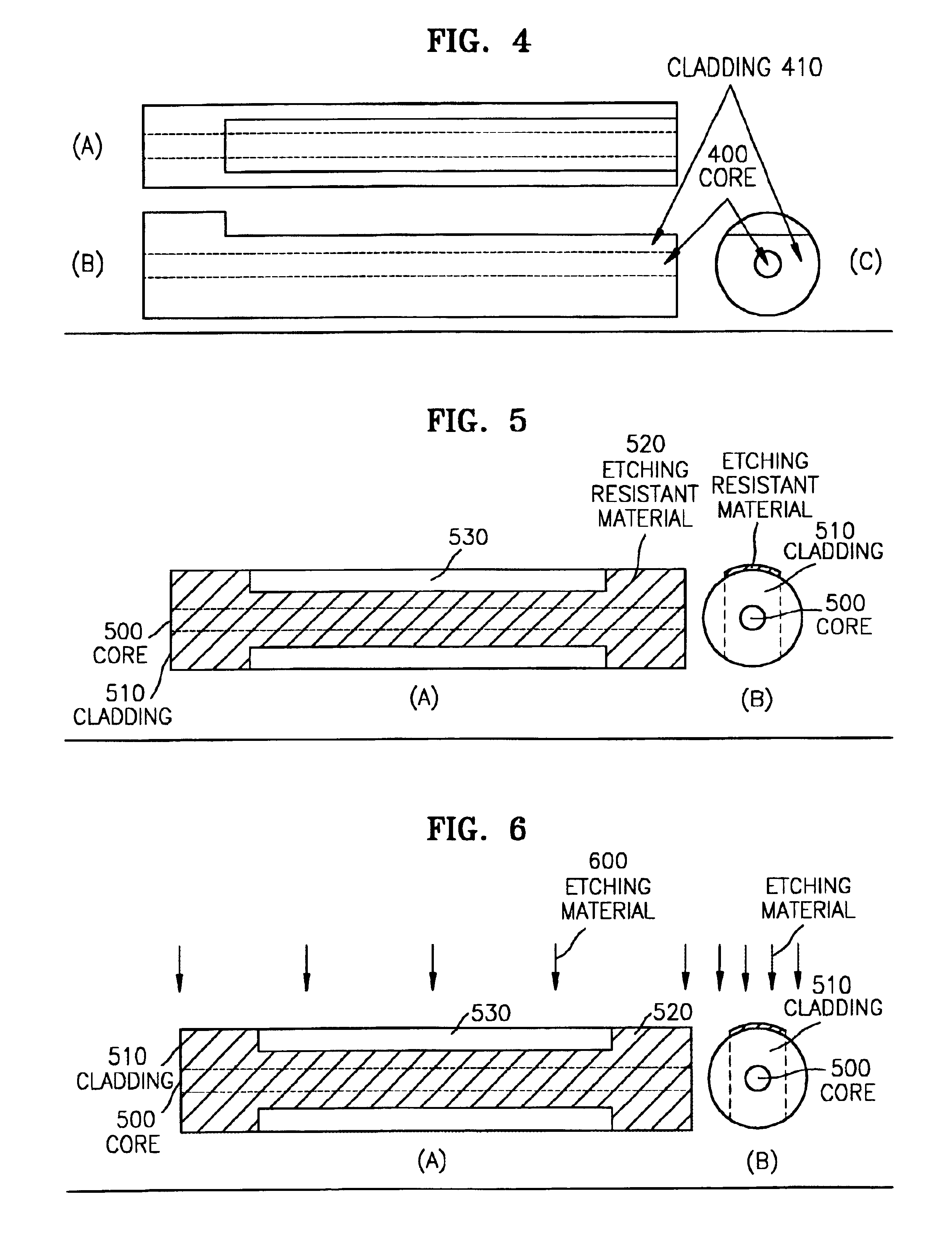
A method of fabricating a poled fiber and a dispersion compensator. The method including patterning to cover an etching-resistant material on the body portions of the cladding and on one end or both ends of the optical fiber excluding the portions to be grooved in the longitudinal direction, etching the bare portions of the cladding excluding the portions covered with the etching-resistant material, evaporating electrodes on the etched portions and applying a voltage to the electrodes, and inducing periodic poling generating optical phenomenon of the second-order nonlinearity to the optical fiber through the patterned electrodes. The compensator including a periodic poled fiber to generate a phase conjugate wave of a difference frequency between a pump light and a signal light received from a fiber coupler, and a filter to pass the phase conjugate wave coming out from the periodic poled fiber.

Description

BACKGROUND OF THE INVENTION1. Field of the InventionThe present invention is related to a poled fiber which uses the second-order optical nonlinearity, a method of fabricating the poled fiber, and a dispersion compensator which can compensate for the chromatic dispersion in a single mode fiber.2. Description of the Related ArtGenerally, the polarization P of a medium and the electric field E of applied light are related as follows:P=χ(1)E+χ(2)EE+χ(3)EEE+ . . .where χ(n) denotes the coefficient of the n-th order polarizability. If χ(2) is not equal to 0, the optical phenomenon of the second-order nonlinearity such as the second harmonic generation or the difference frequency generation is induced. In case of an optical fiber χ(2) is equal to 0 because the silica glass used for the optical fiber is the material that possesses the property of centro-symmetry. However, if a static electrical field is applied to the fiber at a high temperature, the characteristic of the second-order nonl...

Claims


Application Information

Patent Timeline
Patent Type & Authority Patents(United States)
IPC IPC(8): G02F1/355G02B6/02G02B6/34G02F1/35G02B6/00
CPCG02F1/3558G02B6/29394G02F2201/02G02B6/00
Inventor KIM, JONGBAEPARK, SAHNGGICHOI, YONGGYUJU, JUNGJIN
Owner ELECTRONICS & TELECOMM RES INST
Learn More