System for dynamic diagnosis of apparatus operating conditions

a dynamic diagnosis and operating condition technology, applied in the field of test and diagnosis systems, can solve the problems of difficult navigation through products, difficult to hook up all the necessary equipment, etc., and achieve the effect of adding structural and operating advantages

Inactive Publication Date: 2005-01-18
SNAP ON INC
View PDF28 Cites 83 Cited by
  • Summary
  • Abstract
  • Description
  • Claims
  • Application Information

AI Technical Summary

Benefits of technology

It is a general object of the invention to provide an improved diagnostic system which avoids the disadvantages of prior such systems while affording additional structural and operating advantages.
An important feature of the invention is the provision of a diagnostic system which will guide the user in the selection of tests to be performed and minimize the performance of needless tests.
Yet another feature of the invention is the provision of a diagnostic system of the type set forth which facilitates modification and updating to include information on problems and cures experienced in the field over the life of an apparatus under test.
Still another feature of the invention is the provision of a diagnostic system of the type set forth which can be readily integrated with pre-existing diagnostic hardware platforms.

Problems solved by technology

They may take considerable time to hook up all the necessary leads and perform the comprehensive tests, and the user must decide which product to use and how the test data should be integrated into an overall diagnosis.
However, such products are difficult to navigate through to find the information needed for diagnosis and repair and they are typically based only on original equipment diagnostic information, and may not contain information on problems experienced in the field over the life of the vehicle.

Method used


Image

  • System for dynamic diagnosis of apparatus operating conditions
  • System for dynamic diagnosis of apparatus operating conditions
  • System for dynamic diagnosis of apparatus operating conditions

Examples


Embodiment Construction

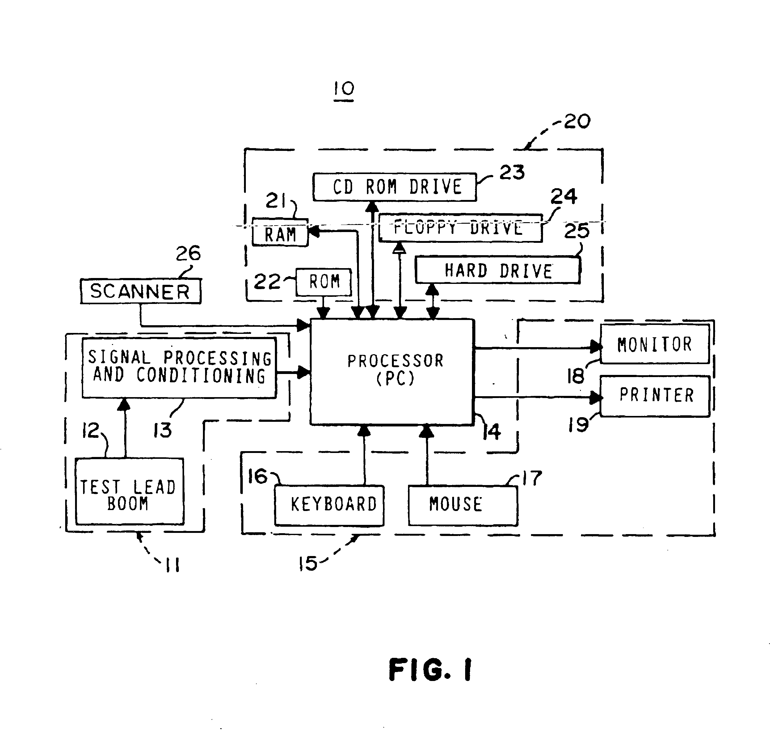
Referring to FIG. 1, there is illustrated a functional block diagram of a diagnostic platform 10 incorporating the diagnostic system of the present invention. The platform 10 is illustrated as relating to an engine analyzer system but, as was indicated above, it could be applicable to other types of vehicle or non-vehicle diagnostic systems. The platform 10 includes engine analyzer hardware 11, which typically includes a test lead boom 12, including a plurality of test leads and sensors adapted to be connected to various points of an associated vehicle engine, and signal processing and conditioning hardware 13 for interfacing the test lead boom to a central processor 14. Preferably, the diagnostic platform 10 is a personal computer (“PC”)-WINDOWS®-based platform, such as that provided in the Suns® System 500 engine analyzer sold by Snap-on Diagnostics, but it will be appreciated that the present invention would also be usable with other types of engine analyzer systems, such as that...


PUM


Abstract

A diagnostic platform includes a processor, storage media and user interfaces, including a display screen, the processor being coupled to engine analyzer hardware and adapted to be coupled to a scanner for downloading data from vehicle on-board computers. The system stores libraries of information regarding vehicle identifications, drivability symptoms exhibited by vehicles, vehicle system and component tests and service codes which can be registered by the vehicle on-board computer. System software permits the user to input an identification of the vehicle under test and, in one mode of operation, displays a library of faults, such as symptoms or service codes, from which the user can select those exhibited by the vehicle, whereupon the system selects from the test library those tests pertinent to diagnosis of the causes of the selected faults and displays them in a hierarchically ranked order based on likelihood of successful diagnosis of the faults. The user can then select and initiate any displayed test. In other modes, the system initially displays one of the libraries of system or component tests, from which the user selects those deemed appropriate, whereupon the system highlights icons which can be selected for initiating pertinent test procedures. Selected test procedures may include links to the engine analyzer or scanner hardware or other appropriate test modules.

Description

BACKGROUND OF THE INVENTIONThe present invention relates generally to test and diagnosis systems for machines or other operating apparatus, and has particular application to automotive vehicles, particularly vehicles powered by internal combustion engines. While the invention is described in the context of an engine analyzer system, the principles of the present invention are usable with other types of vehicle diagnostic systems, such as air conditioning testing and servicing systems, wheel balancing systems, automotive gas emissions analysis systems, and the like, and are also usable with non-automotive apparatus.A number of different types of diagnostic tools have been heretofore used to assist in diagnosis and repair of fault conditions in automotive vehicles. Such tools include engine analyzers, which are designed to monitor a variety of operating conditions of an internal combustion engine, and scanners for downloading data from vehicle on-board computers. In addition, diagnost...

Claims


Application Information

Patent Timeline
Patent Type & Authority Patents(United States)
IPC IPC(8): G01M17/007A61B5/00G07C5/08
CPCG01M17/007G01M17/00G01D21/00G07C5/0808A61B5/00
Inventor ROTHER, PAUL J.
Owner SNAP ON INC
Why Eureka
Try Eureka