Variable area plug nozzle

a variable area and nozzle technology, applied in machine/engine, vessel construction, marine propulsion, etc., can solve the problems of increasing engine weight, increasing noise, and generating additional noise, so as to reduce noise, increase the available flow area, and reduce the effect of velocity

Inactive Publication Date: 2005-01-25
AERONAUTICAL CONCEPT OF EXHAUST +1
View PDF7 Cites 47 Cited by
  • Summary
  • Abstract
  • Description
  • Claims
  • Application Information

AI Technical Summary

Benefits of technology

A center plug is configured for variable area use in an exhaust nozzle. A forward portion of the plug includes an inlet having a closing flap therein, and an aft portion of the plug includes an outlet. The flap is selectively open during aircraft takeoff operation for bypassing a portion of core exhaust flow through the plug, with the flap being closed at cruise operation. Opening the flap correspondingly increases the available flow area for discharging the exhaust flow for reducing velocity thereof, and attenuating noise.

Problems solved by technology

The high velocity exhaust flow generates significant noise during operation, with additional noise being generated by the fan exhaust, as well as by the rotating components of the engine.
However, noise attenuation features typically add weight to the engine, and it is desirable to minimize engine weight in an aircraft turbofan engine.

Method used


Image

  • Variable area plug nozzle
  • Variable area plug nozzle
  • Variable area plug nozzle

Examples


Embodiment Construction

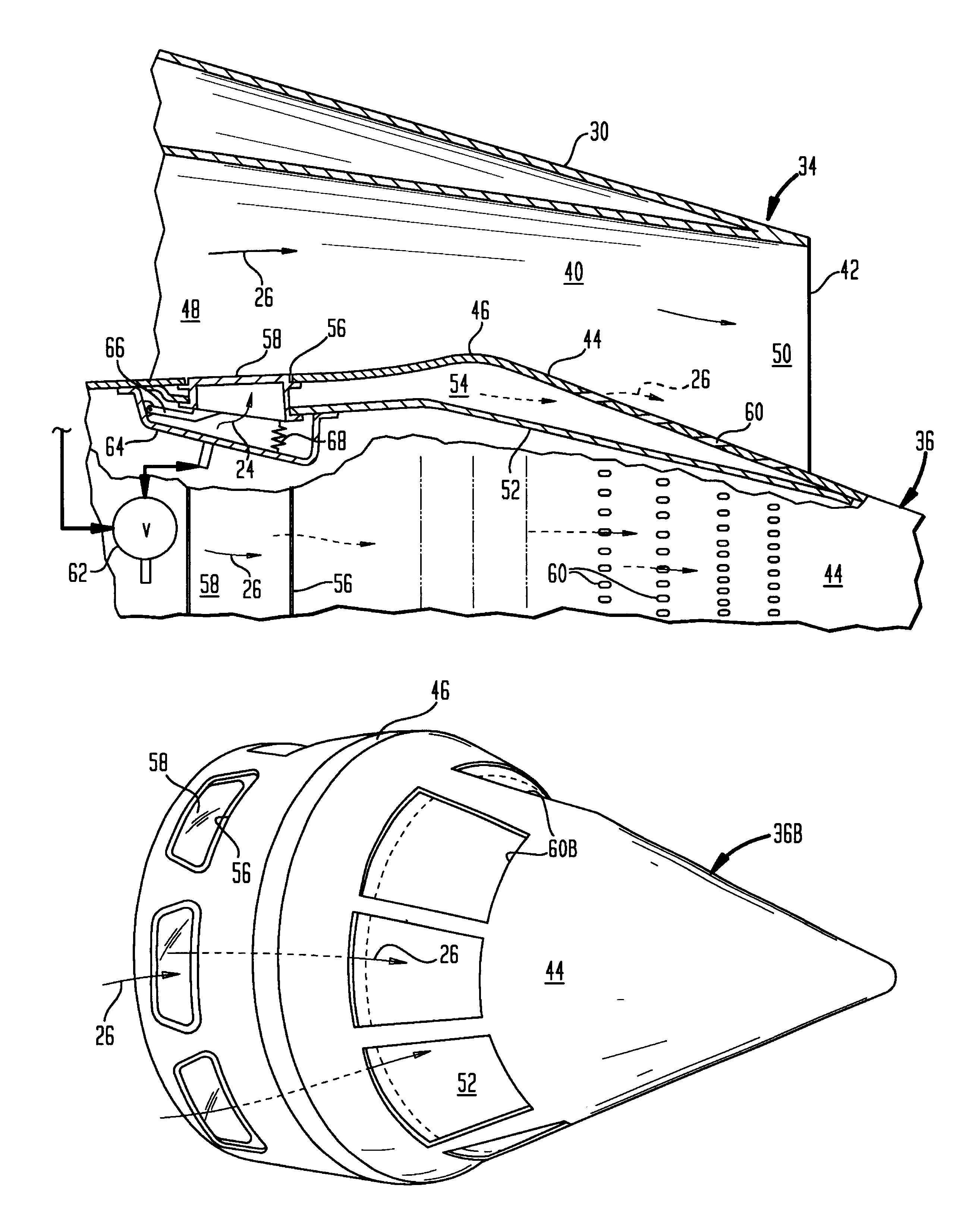
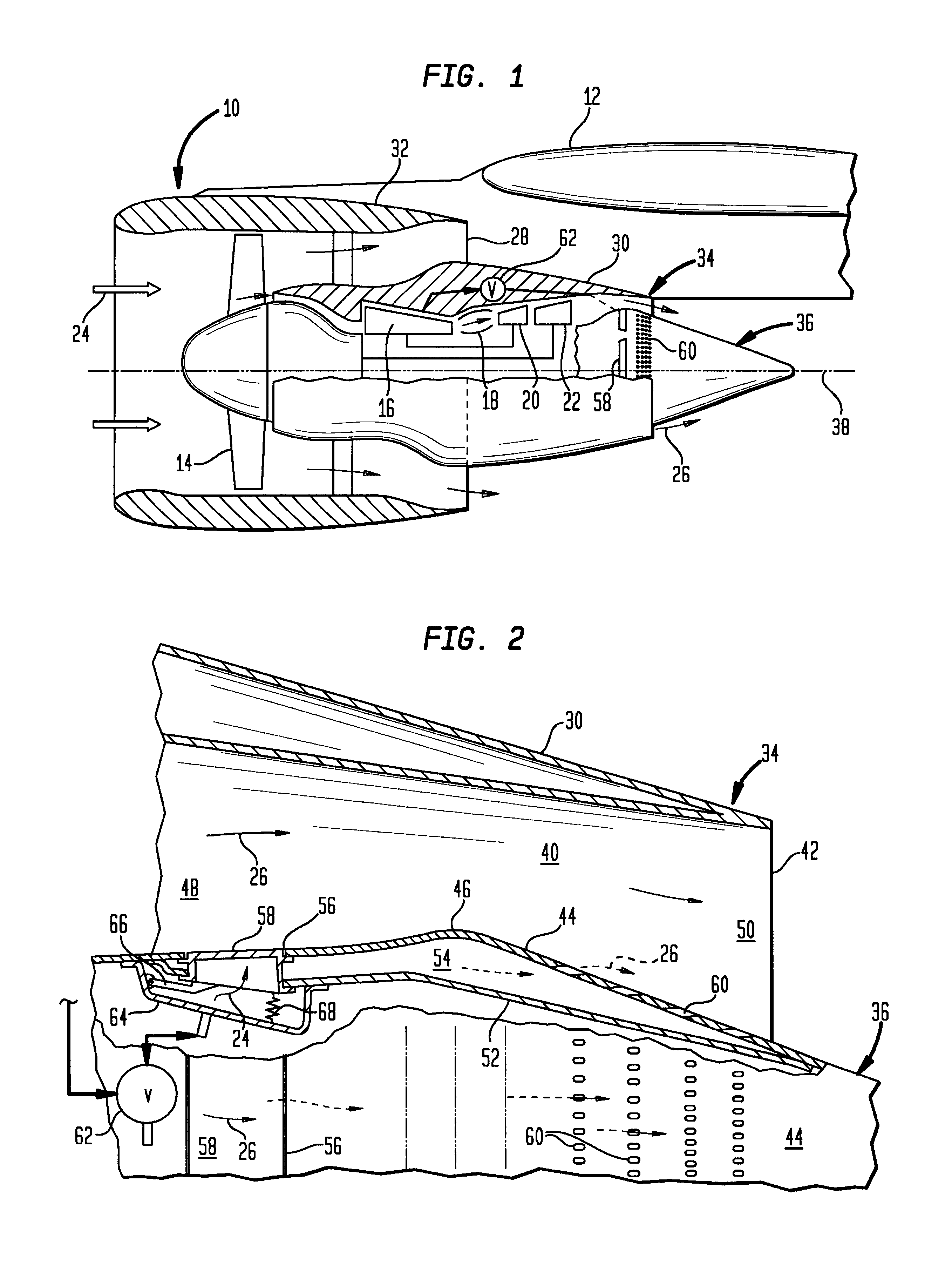
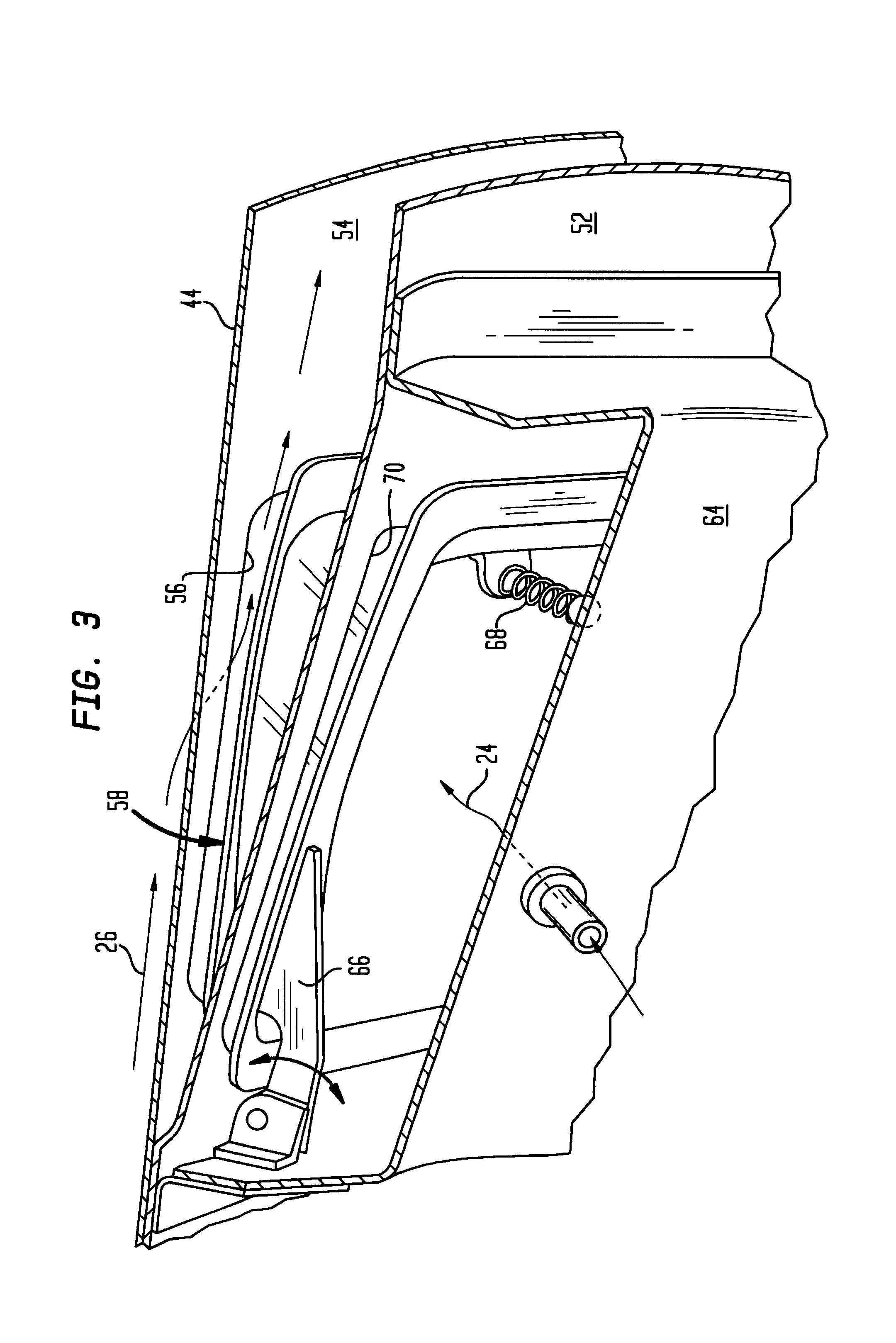
Illustrated in FIG. 1 is an exemplary turbofan aircraft gas turbine engine 10 mounted by a pylon to the wing of an aircraft 12, shown in part. The engine includes in serial flow communication a fan 14, multistage axial compressor 16, annular combustor 18, high pressure turbine 20, and low pressure turbine 22.

During operation, air 24 is pressurized in the compressor and mixed with fuel in the combustor for generating hot combustion gases 26 which flow through the high and low pressure turbines that extract energy therefrom. The high pressure turbine powers the compressor through a shaft therebetween, and the low pressure turbine powers the fan through another shaft therebetween.

The exemplary turbofan engine illustrated in FIG. 1 is in the form of a high bypass ratio engine in which most of the air pressurized by the fan bypasses the core engine itself for generating propulsion thrust. The fan air 24 is discharged from the engine through a substantially annular fan exhaust nozzle 28 d...


PUM


Abstract

A center plug is configured for variable area use in an exhaust nozzle. A forward portion of the plug includes an inlet having a closing flap therein, and an aft portion of the plug includes an outlet. The flap is selectively open during aircraft takeoff operation and up to a preset climb altitude for bypassing a portion of core exhaust flow through the plug, with the flap being closed from preset altitude and cruise operation. Opening the flap correspondingly increases the available flow area for discharging the exhaust flow for reducing velocity thereof, and attenuating noise.

Description

BACKGROUND OF THE INVENTIONThe present invention relates generally to turbofan aircraft gas turbine engines, and, more specifically, to noise attenuation therein.In an aircraft turbofan engine, air is pressurized in a compressor and mixed with fuel in a combustor for generating hot combustion gases which flow downstream through turbine stages that extract energy therefrom. A high pressure turbine powers the compressor, and a low pressure turbine powers a fan disposed upstream of the compressor.The combustion gases are discharged from the core engine through an annular exhaust nozzle, and the fan air is discharged through another exhaust nozzle surrounding the core engine. The majority of propulsion thrust is provided by the pressurized fan air discharged from the fan exhaust nozzle, and remaining thrust is provided from the combustion gases discharged from the core exhaust nozzle.The core exhaust flow is discharged from the core nozzle at high velocity and then mixes with the fan ai...

Claims


Application Information

Patent Timeline
Patent Type & Authority Patents(United States)
IPC IPC(8): F02K1/06F02K1/42F02K1/78F02K1/00
CPCF02C9/18F02K1/06F02K1/42F02K1/805F02K3/06F02K1/78F05D2260/96
Inventor LAIR, JEAN-PIERRE
Owner AERONAUTICAL CONCEPT OF EXHAUST
Why Eureka
Try Eureka