Suction muffler for a refrigerating machine

Inactive Publication Date: 2005-01-25
DANFOSS COMPRESSORS +1
View PDF3 Cites 13 Cited by
  • Summary
  • Abstract
  • Description
  • Claims
  • Application Information

AI Technical Summary

Benefits of technology

Preferably, an insert is arranged in the housing, said insert dividing the chamber into an upper chamber and a lower chamber and having its own oil collecting room at the bottom end of the upper chamber, the oil discharge opening of said oil collecting room ending in the lower chamber. This gives the same effect as the oil collecting room at the bottom end of the lower chamber, that is, the oil can discharge from the upper chamber and reach the lower chamber via the oil discharge opening. A pressure difference between the upper chamber and the lower chamber is equalised by the hydrostatic pressure at the bottom end of the fluid column, which is created in the oil collecting room of the upper chamber.
It is preferred that the insert has a pipe-like insert nozzle, in which the oil collecting room is arranged, and which extends into the lower chamber. This ensures that a fluid column can also be created relatively fast even when a small oil volume is present. The use of the insert nozzle causes that the oil collecting room of the upper chamber also has a relatively small cross-section. This embodiment has the advantage that only a small volume of the lower chamber is occupied and that only a relatively small oil surface is available, from which oil can be entrained. This keeps the internal oil circulation small.
Preferably, the bottom end of

Problems solved by technology

In such suction mufflers, the problem is that the oil from the refrigerant flow settling in the chamber cannot immediately flow to the oil sump during operation of the compressor.
With a long and uninterrupted operation period, a considerable amount of oil can gather in the chamber, which causes several disadvantages.
Firstly, oil, which is required for lubr

Method used


Image

  • Suction muffler for a refrigerating machine
  • Suction muffler for a refrigerating machine
  • Suction muffler for a refrigerating machine

Examples


Embodiment Construction

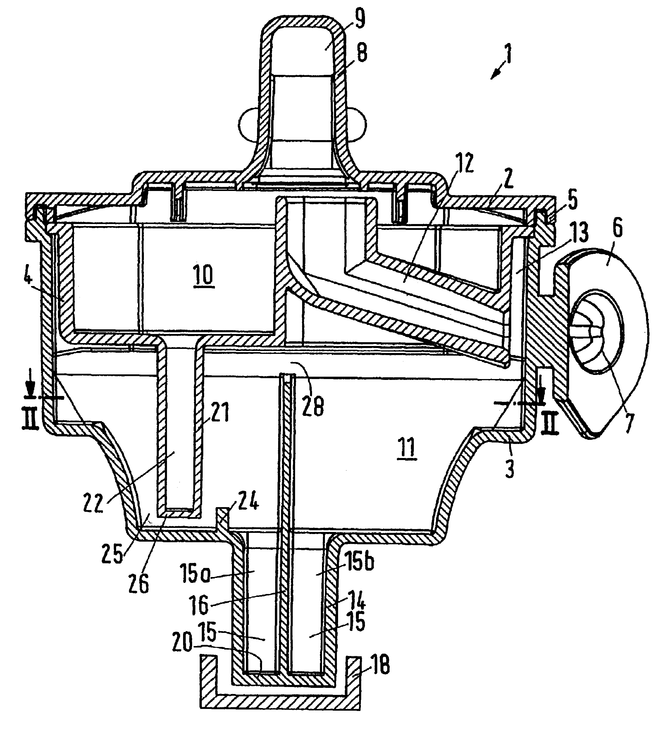
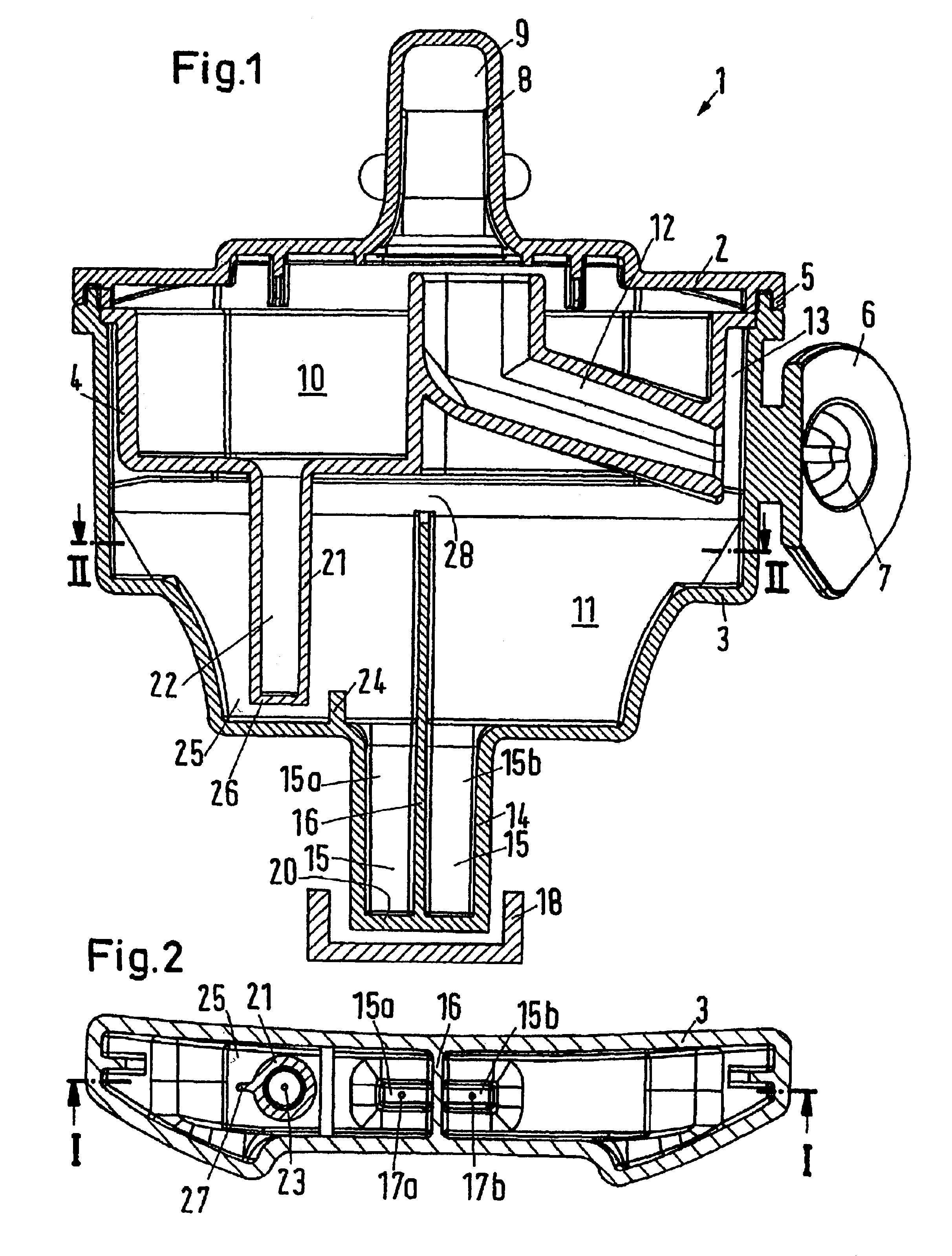
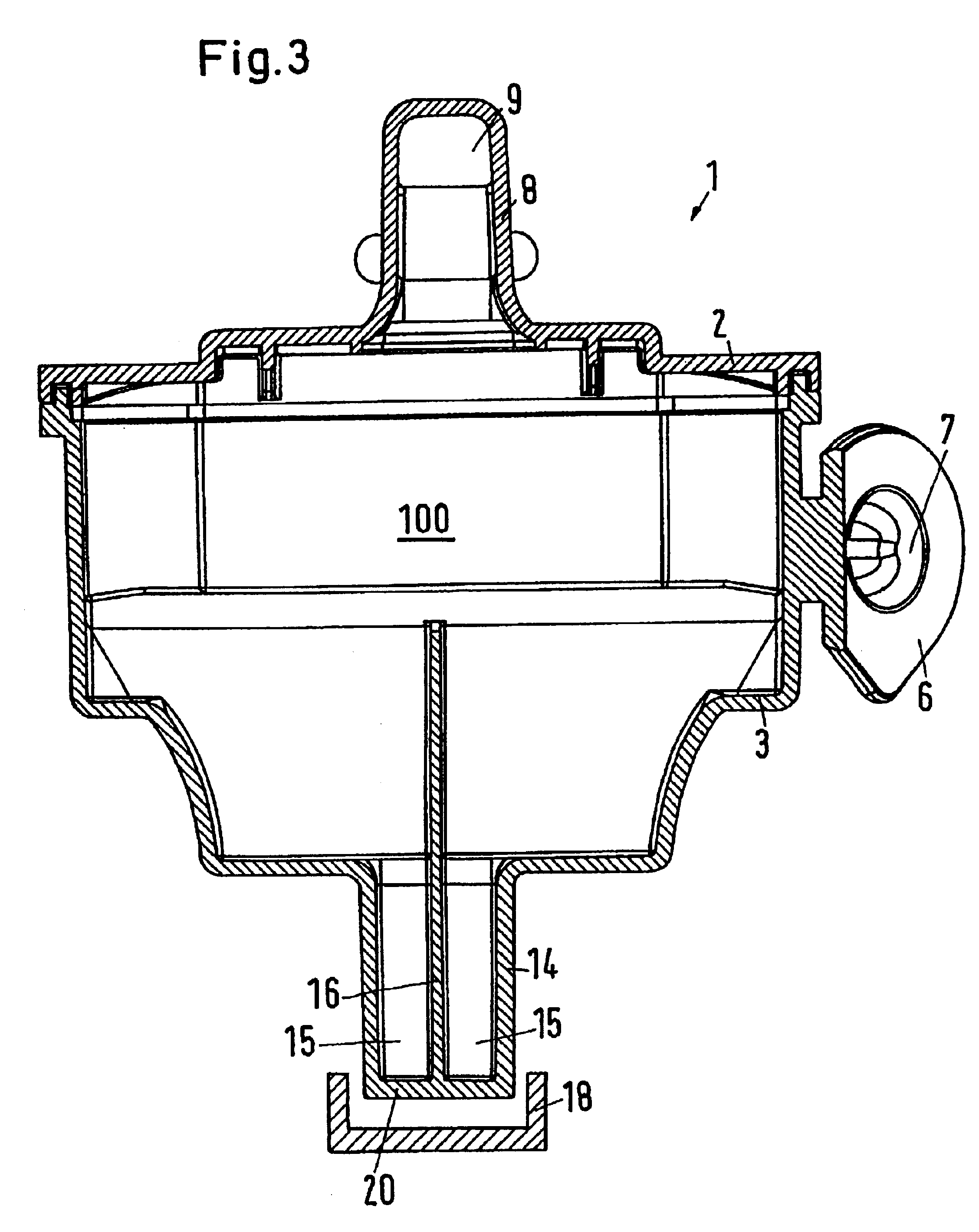
A suction muffler 1 has a housing with an upper part 2, a lower part 3 and an insert 4. Upper part 2, lower part 3 and insert 4 are made of a plastic material and are connected with each other in the area of a connecting joint 5 by means of bonding or welding.

The lower part 3 has an inlet nozzle 6 with an inlet opening 7. In the upper part 2 is formed an outlet nozzle 8 with an outlet opening 9. The insert 4 divides the housing into an upper chamber 10 and a lower chamber 11. The two chambers 10, 11 are connected with each other via a channel 12, which is formed in the insert 4. The channel 12 is arranged next to an end of the inlet opening 7, a slot 13 being provided between the inlet opening 7 and the end of the channel, said slot being connected with the lower chamber 11.

The lower part 3 has at its lower end a housing nozzle 14, which extends downward from the bottom side of the lower part 3. All statements refer to the gravity direction. In the housing nozzle 14 is formed an oil...


PUM


Abstract

The invention concerns a suction muffler for a refrigerating machine with a housing, in which at least one chamber is arranged and which has an inlet opening (7), an outlet opening and an oil discharge opening.
It is endeavoured to avoid that too much oil remains in the chamber.
For this purpose, an oil collecting room is arranged to be connected to the bottom end of the chamber, the oil discharge opening being arranged at the bottom end of said oil collecting room.

Description

CROSS-REFERENCE TO RELATED APPLICATIONThis application is entitled to the benefit of and incorporates by reference essential subject matter disclosed in German Patent Application No. 102 05 487.8 filed on Feb. 9, 2002.FIELD OF THE INVENTIONThe invention concerns a suction muffler for a refrigerating machine with a housing, in which at least one chamber is arranged and which has an inlet opening, an outlet opening and an oil discharge opening.BACKGROUND OF THE INVENTIONA suction muffler of this kind is known from DE 36 45 083 C2. It is particularly applied in connection with small, enclosed refrigerating machines, as used in the domestic area for refrigerators and freezers. The refrigerant gas sucked in through the suction muffler always contains an amount of oil, part of which precipitates inside the muffler. This oil gathers in the chamber. At the bottom of the chamber an oil discharge opening is provided, through which the precipitated oil can run out of the chamber. However, this...

Claims


Application Information

Patent Timeline
IPC IPC(8): F04B39/00F04C29/06F04C29/02
CPCF04B39/0061F04C29/065F04C29/026
Inventor SVENDSEN, CHRISTIANNISSEN, JENS ERIKSVENDSEN, MORTEN
Owner DANFOSS COMPRESSORS
Why Eureka
Try Eureka