Collision attenuating system

a technology of attenuating system and attenuating force, which is applied in the direction of bumpers, pedestrian/occupant safety arrangements, vehicular safety arrangements, etc., can solve the problems of difficult stopping of railroad trains, inability to steer railroad trains to avoid pedestrians and other motor vehicles, and heavy relative to pedestrians, so as to reduce the severity of an impact

Inactive Publication Date: 2005-01-25
PAYNE THOMAS S +1
View PDF29 Cites 14 Cited by
  • Summary
  • Abstract
  • Description
  • Claims
  • Application Information

AI Technical Summary

Benefits of technology

An object of the present invention is to provide an improved collision attenuating system to better reduce the severity of an impact, which cann

Problems solved by technology

Railroad trains are heavy vehicles that are difficult to stop in emergency situations.
Furthermore, railroad trains cannot be steered to avoid pedestrians and other motor vehicles that inadvertently cross the path of a moving railroad train.
Railroad trains are extremely heavy relative to pedestrians as well as most motor vehicles including automobiles, sport-utility vehicles, trucks, vans, and buses.
Unfortunately, due to these factors, collisions between railroad trains and pedestrians or between railroad trains and motor vehicles result all too often in fatalities for the pedestrians or for the occupants of the impacted motor vehicles.
Unfortunately, pedestrians and motor vehicle operators on occasion accidentally miss, ignore, or deliberately circumvent these warning syst

Method used


Image

  • Collision attenuating system
  • Collision attenuating system
  • Collision attenuating system

Examples


Embodiment Construction

Reference will now be made in detail to the preferred embodiments of the invention, examples of which are illustrated in the accompanying drawings. While the invention will be described in conjunction with the preferred embodiments, it will be understood that they are not intended to limit the invention to those embodiments. On the contrary, the invention is intended to cover alternatives, modifications and equivalents, which may be included within the spirit and scope of the invention as defined by the appended claims.

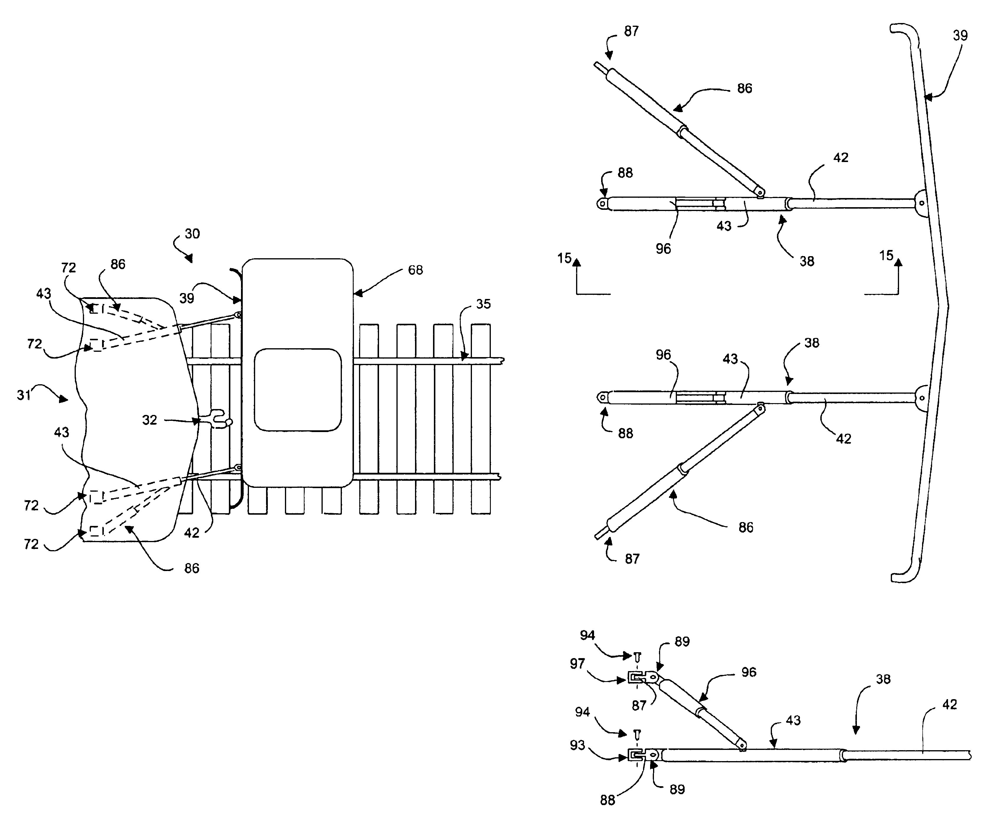
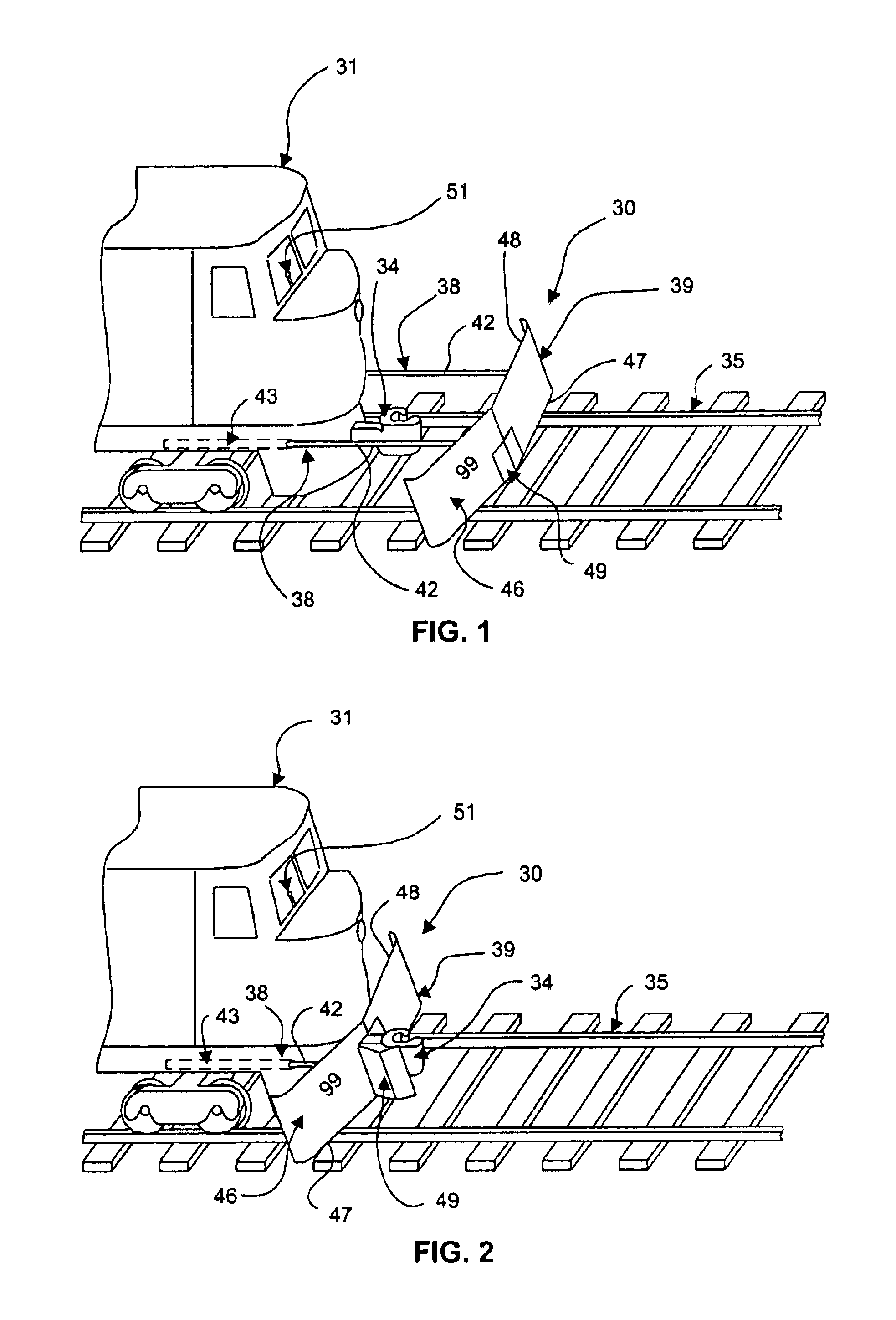
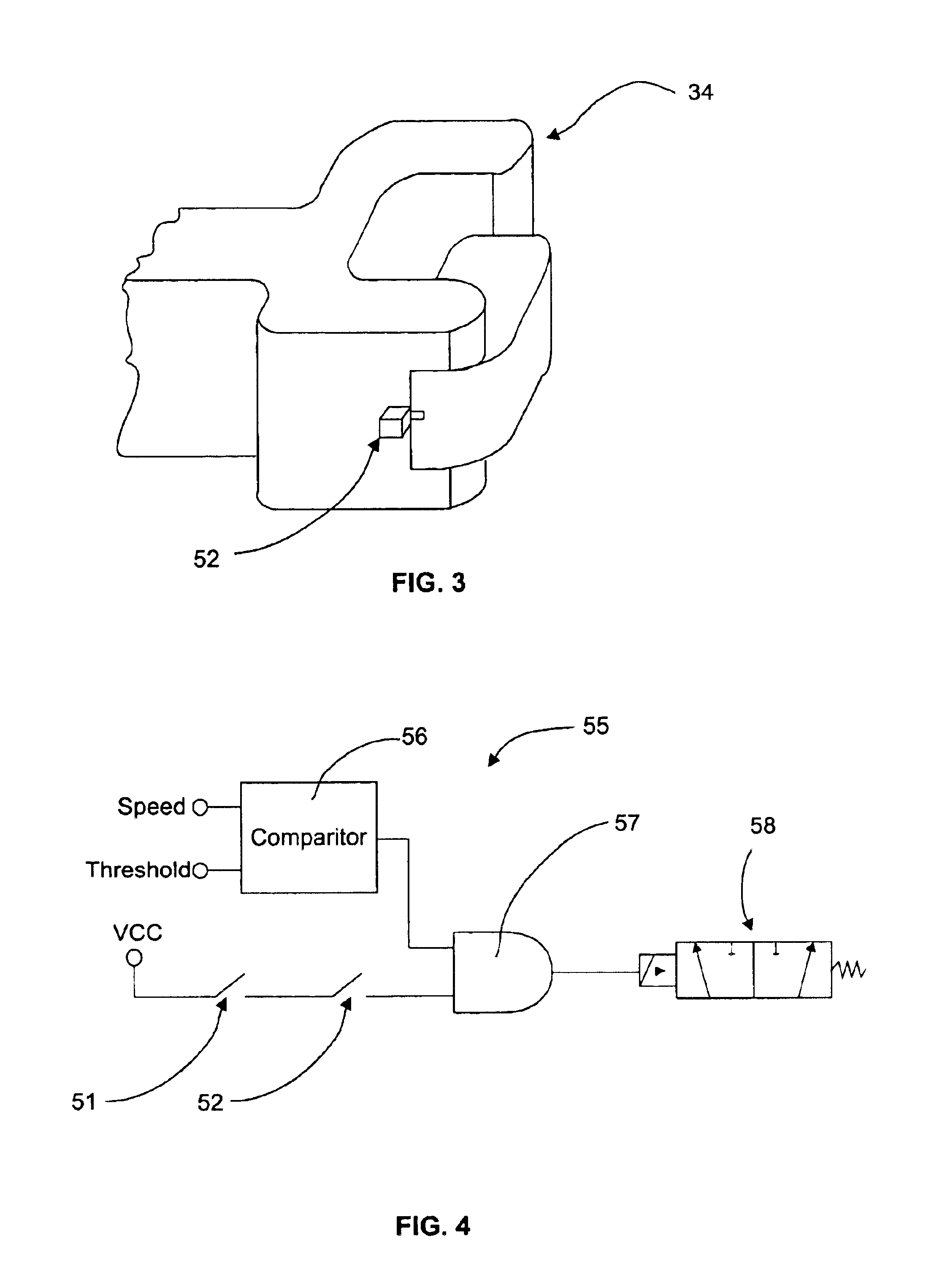
Turning now to the drawings, wherein like components are designated by like reference numerals throughout the various figures, attention is directed to FIG. 1, which shows a collision attenuator 30 mounted on the front end of a locomotive 31, which locomotive is equipped with a coupler 34 and is configured for motion along a railway 35. It will be understood that the collision attenuator can also be configured to be mounted on other types of rail cars including, but n...


PUM


Abstract

A collision attenuator for a vehicle including an energy absorbing cylinder, a mounting assembly adapted to secure the energy absorbing cylinder to an end of the vehicle, a contact plate mounted to the energy absorbing cylinder, a control valve for extending and retracting the energy absorbing cylinder in order to move the contact plate with respect to the end of the vehicle. A comparator is operably coupled with the control valve, wherein the comparator is configured to adjust the energy absorbing cylinder based upon a speed signal indicative of the speed of the moving vehicle. A coupler detector is operably coupled with the control valve, wherein the coupler detector inhibits the extension of the energy absorbing cylinder unless the coupler detector determines that the coupler is open. A pivot assembly pivotally secures the contact plate to the energy absorbing cylinder allowing the contact plate to pivot laterally about an upright axis with respect to the energy absorbing cylinder. A quick-release mechanism detachably secures the energy absorbing assembly to the end of the vehicle. A vehicle support portion extends horizontally forward adjacent a bottom edge of the contact plate.

Description

BACKGROUND OF THE INVENTION1. Field of the InventionThe present invention relates, in general, to collision attenuators and, more particularly, to improved collision attenuators for the front ends of railroad trains or other moving vehicles and to methods for their use.2. Description of Related ArtRailroad trains are heavy vehicles that are difficult to stop in emergency situations. Furthermore, railroad trains cannot be steered to avoid pedestrians and other motor vehicles that inadvertently cross the path of a moving railroad train. Railroad trains are extremely heavy relative to pedestrians as well as most motor vehicles including automobiles, sport-utility vehicles, trucks, vans, and buses. The front of a locomotive or a railroad car is typically constructed of a large rigid steel structure that yields minimally, if at all, in the event of a collision with a pedestrian or a motor vehicle. Unfortunately, due to these factors, collisions between railroad trains and pedestrians or ...

Claims


Application Information

Patent Timeline
IPC IPC(8): B61F19/00B61F19/06B60R21/34B60R19/20B60R19/00B60R19/18
CPCB61F19/06B60R19/205B60R2019/005B60R21/34
Inventor PAYNE, THOMAS S.PAYNE, JAMES M.
Owner PAYNE THOMAS S
Why Eureka
Try Eureka