Fuel injector with dual control valve

a fuel injector and control valve technology, applied in the direction of fuel injecting pumps, machines/engines, non-mechanical valves, etc., can solve the problems of high efficiency and inefficiency of pilot injection operation

Inactive Publication Date: 2005-01-25
INT ENGINE INTPROP CO LLC
View PDF32 Cites 20 Cited by
  • Summary
  • Abstract
  • Description
  • Claims
  • Application Information

AI Technical Summary

Benefits of technology

The present invention is a hydraulically actuated, intensified fuel injector includes a controller achieving a desired injection control strategy by selectively independently porting actuating fluid to and venting actuating fluid from an intensifier piston to control the compressive stroke of the intensifier piston and selectively independently porting actuating fluid to and venting actuating fluid from a needle valve to control the opening and closing of the needle valve during the injection event. The present invention is further a method of control.

Problems solved by technology

Therefore reversing the motion of the intensifier 84 to achieve pilot injection operation is inefficient.
With such relatively massive devices as the spool valve 120 and the intensifier piston 84, this is highly inefficient.

Method used


Image

  • Fuel injector with dual control valve
  • Fuel injector with dual control valve
  • Fuel injector with dual control valve

Examples


Embodiment Construction

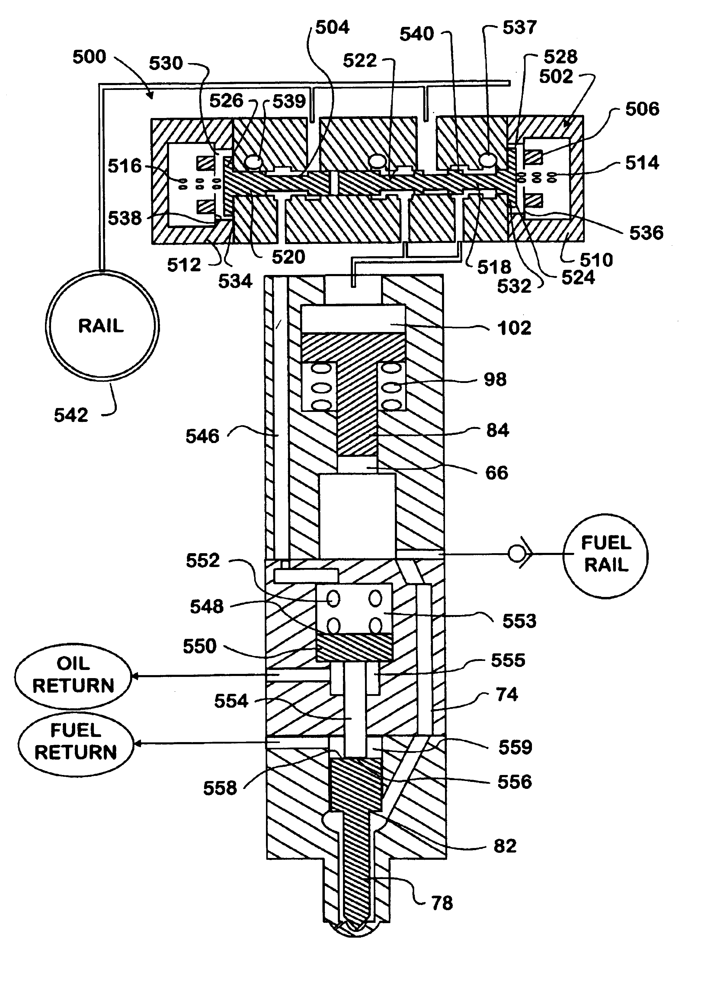
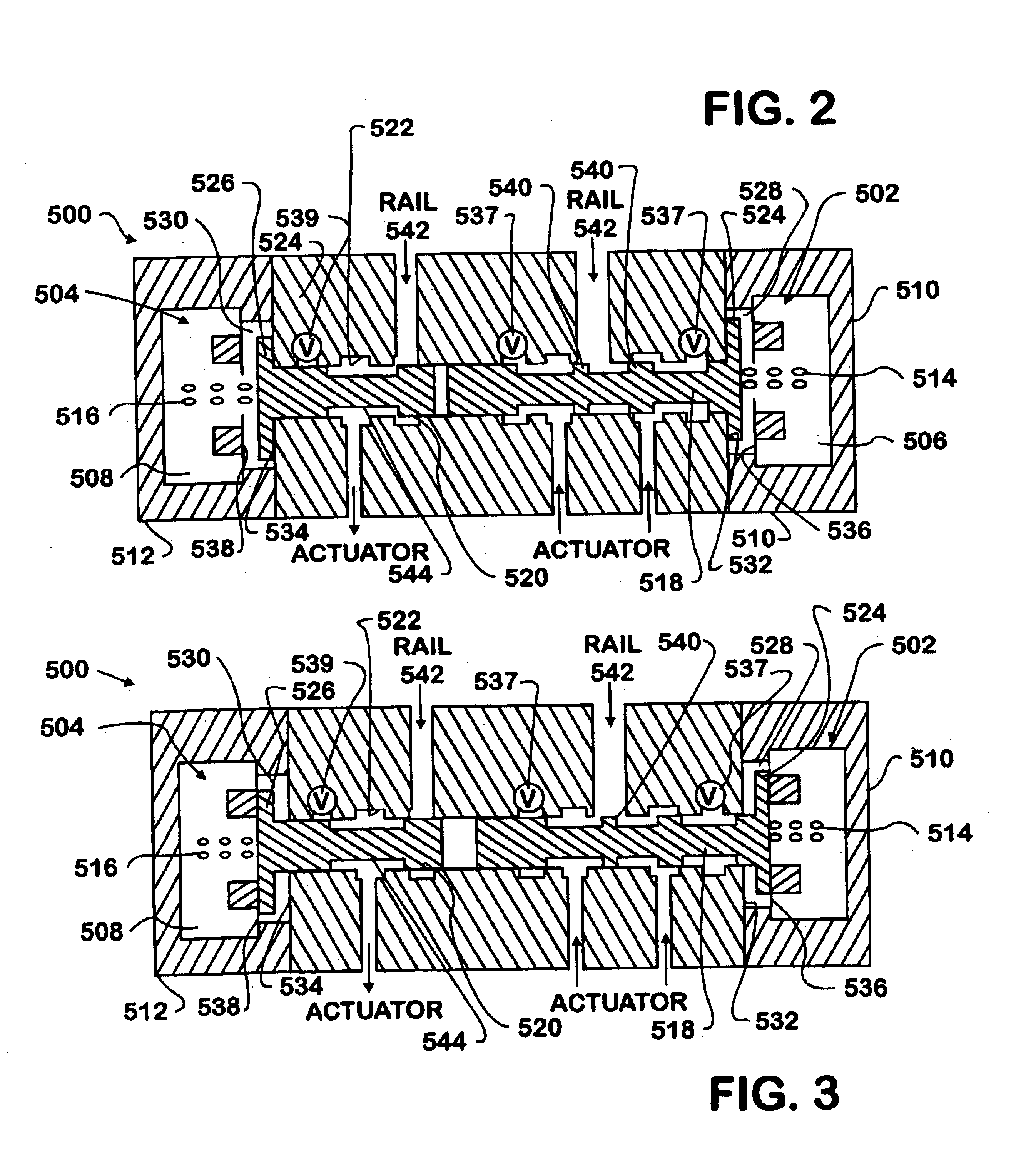
The present invention is related to the dual control valve, shown generally at 500 in the FIGS. 2 and 3, and the application of the dual control valve 500 to a fuel injection system in FIG. 4.

Referring to FIGS. 2 and 3, the dual control valve 500 has two major components, pressure control valve 502 and timing control valve 504. The pressure control valve 502 and timing control valve 504 of the control valve 500 each include a dedicated respective control coil 506, 508 and cap assemblies 510, 512, respective return springs 514, 516. The pressure control valve 502 includes a single balanced spool valve 518. The timing control valve 504 is comprised of a half spool valve 520 (The timing control valve 504 may also be a poppet valve). Both valves 502, 504 are depicted being on the same longitudinal axis and in this configuration may be installed from both ends in a bore 522 defined in a common housing 524. It should be noted that the valves 502, 504 need not be in the depicted coaxial di...


PUM


Abstract

A hydraulically actuated, intensified fuel injector includes a controller achieving a desired injection control strategy by selectively independently porting actuating fluid to and venting actuating fluid from an intensifier piston to control the compressive stroke of the intensifier piston and selectively independently porting actuating fluid to and venting actuating fluid from a needle valve to control the opening and closing of the needle valve during the injection event. A method of control is further included.

Description

TECHNICAL FIELDThe present application relates to internal combustion engine valve control. More particularly, the present application relates to independent needle valve control in a hydraulically actuated, intensified fuel injector.BACKGROUND AND PRIOR ARTReferring to the prior art drawings, FIG. 1 shows a prior art fuel injector 50. The prior art injector 50 is substantially as described in U.S. Pat. No. 5,460,329 to Sturman. A fuel injector having certain similar features may be found in U.S. Pat. No. 5,682,858 to Chen et al. The fuel injector 50 is typically mounted to an engine block and injects a controlled pressurized volume of fuel into a combustion chamber (not shown). The injector 50 is typically used to inject diesel fuel into a compression ignition engine, although it is to be understood that the injector could also be used in a spark ignition engine or any other system that requires the injection of a fluid.The fuel injector 50 has an injector housing 52 that is typica...

Claims


Application Information

Patent Timeline
Patent Type & Authority Patents(United States)
IPC IPC(8): F02M59/10F02M57/00F02M57/02F02M59/00F02M59/46F02M45/12F02M47/02F02M45/00
CPCF01L9/02F02M45/12F02M47/027F02M57/025F02M63/0061F02M59/466F02M63/0017F02M63/004F02M63/0049F02M59/105F01L2009/028F01L9/10F01L9/18
Inventor LEI, NING
Owner INT ENGINE INTPROP CO LLC
Why Eureka
Try Eureka