Fluid exit in reaction chambers

a technology of reaction chambers and liquid exits, applied in the field of chambers, can solve the problems of many steps, inability to reliably provide consistent ambient humidity levels, and wrong products, and achieve the effect of constant cross-sectional area

Inactive Publication Date: 2005-01-25
AGILENT TECH INC
View PDF45 Cites 60 Cited by
  • Summary
  • Abstract
  • Description
  • Claims
  • Application Information

AI Technical Summary

Benefits of technology

Another embodiment of the present invention is an apparatus for synthesizing a plurality of biopolymers on a support. The apparatus is similar to that described above. At least one wall of the opening is designed such that the opening comprises a contracting section, a section having substantially constant cross-sectional area and a diffusing section. The wall in the contracting section comprises a sloped portion and a curved portion. The sloped portion is very insensitive to the contracting slope and may vary substa

Problems solved by technology

Since many of the reactions are performed stepwise, any failure during the synthesis results in the wrong product.
Since the arrays provide for a large number of different compounds, the process requires many steps.
Such a technique fails to provide reliably consistent ambient humidity levels because of the turbulent flow that is achieved.
Door-based designs suffer from large-scale flow feature generation near the outlet opening and from highly unsteady flow conditions when the door is opened and closed.
The outside air that enters the chamber carries with it moisture from the outside environment,

Method used


Image

  • Fluid exit in reaction chambers
  • Fluid exit in reaction chambers
  • Fluid exit in reaction chambers

Examples


Embodiment Construction

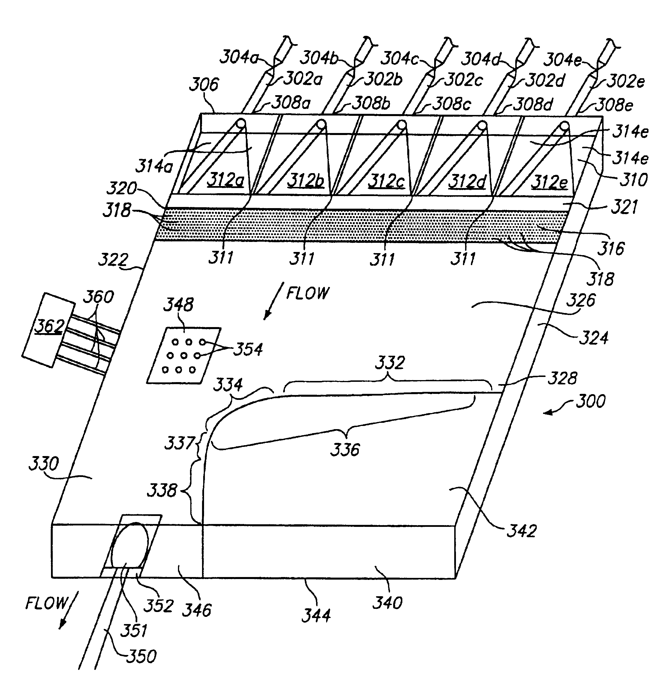
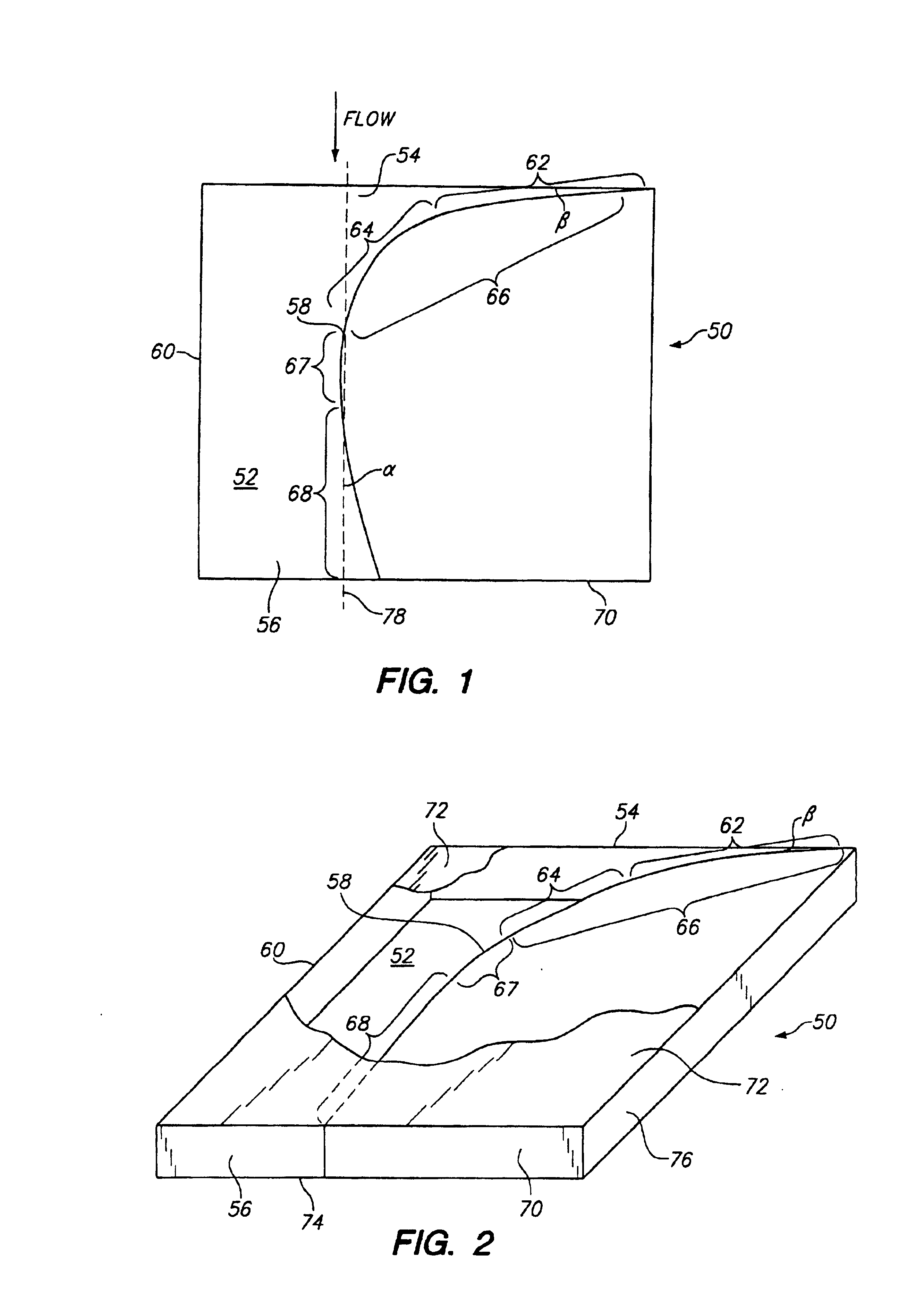
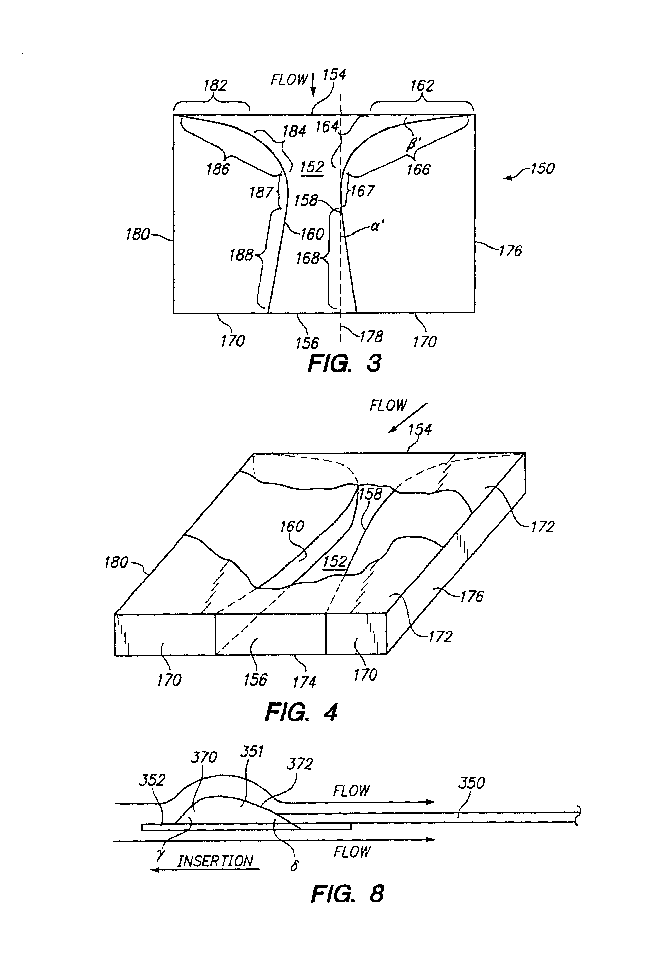
In its broadest aspect the present device comprises a chamber having a first opening and a second opening opposite the first opening. The geometry of the interior wall or walls of the chamber is such as to form a contracting section, a section having substantially constant cross-sectional area and an expansion section therein. Control of the geometric parameters in the contracting section and expansion section assists in avoiding recirculation of fluid flowing from the first opening to the second opening through the chamber and back flow into the chamber through the second opening.

The contracting section results from the initially gradual and subsequently steep tapering of at least one of the internal side walls of the chamber and, in some embodiments, both internal side walls of the chamber. To achieve the gradual and ultimately steep tapering of the side wall, the wall in the contracting section comprises two different sloped portions, the second portion having a slope more steep ...


PUM


Abstract

Apparatus and methods are disclosed for controlling flow of fluid inside a chamber. A device comprises a chamber comprising at least one wall, a first opening for introducing a fluid into the interior of the chamber, and a second opening opposite the first opening. The at least one wall of the chamber is designed to provide a contracting section, a section having substantially constant cross-sectional area and a diffusing section through the chamber from the first opening to the second opening. The device may be employed as a gas outlet in a reaction chamber for conducting reactions where it is desired to control the internal atmosphere of the reaction chamber. The apparatus may be employed in the manufacture of biopolymers on the surface of a support such as an array of biopolymer features on the support. Also disclosed is a holding element for a support wherein the holding element is a low drag body.

Description

BACKGROUND OF THE INVENTIONThis invention relates to chambers for carrying out procedures wherein internal atmospheric conditions, such as, e.g., humidity, of the chamber are controlled. More particularly, the invention relates to devices for carrying out steps in the synthesis of a chemical compound and the exiting of fluids such as gases therefrom. The invention has particular application in the manufacture of supports having bound to the surfaces thereof a plurality of chemical compounds, such as biopolymers, which are prepared on the surface in a series of steps.In the field of diagnostics and therapeutics, it is often useful to attach species to a surface. One important application is in solid phase chemical synthesis wherein initial derivatization of a substrate surface enables synthesis of polymers such as oligonucleotides and peptides on the substrate itself. Support bound oligomer arrays, particularly oligonucleotide arrays, may be used in screening studies for determinatio...

Claims


Application Information

Patent Timeline
IPC IPC(8): B01J19/00B01L3/00C40B40/06C40B40/10C40B50/14C40B60/14
CPCB01J19/0046B82Y30/00C40B60/14B01J2219/00337B01J2219/0036B01J2219/00378B01J2219/00389B01J2219/00477B01J2219/00529B01J2219/00531B01J2219/00585B01J2219/00596B01J2219/00605B01J2219/00659B01J2219/00675B01J2219/00677B01J2219/0072B01J2219/00722B01J2219/00725B01L3/5027C40B40/06C40B40/10C40B50/14B01J2219/00286
Inventor PECK, BILL J.
Owner AGILENT TECH INC
Why Eureka
Try Eureka