Resonant motor system

a technology of resonant motors and motors, applied in the direction of motor/generator/converter stoppers, dynamo-electric gear control, motor/generator/converter stoppers, etc., can solve the problems of inability to adapt or optimize the motor scheme, the difficulty of merging motor and drive in a simple, efficient, economical, and easy-to-assemble combination, and the difficulty of motor and drive integration

Inactive Publication Date: 2005-01-25
PRATT & WHITNEY POWER SYST +1
View PDF10 Cites 45 Cited by
  • Summary
  • Abstract
  • Description
  • Claims
  • Application Information

AI Technical Summary

Problems solved by technology

When running directly from 3-phase AC grid power, no conceivable motor scheme is more adaptable or efficient than the 3-phase AC induction motor.
However, because of the cost and difficulty involved in managing large quantities of permanent magnet material, the brushless DC motor has not proven commercially viable in higher horsepower ranges.
A present problem with electrical motor systems is the difficulty of merging motor and drive in a simple, easily assembled, efficient, and economical combination.
Typically, a drive, in synthesizing an AC waveform to excite an electrical motor from a DC power source employs expensive, high capacity switching devices such as IGBTs (Insulated Gate Bipolar Transistors) to generate a high frequency PWM (Pulse Width Modulation) waveform.
Such drives are characterized by complexity in a customized design that generates and accommodates a PWM waveform, cost in circuit implementation, and inefficiency resulting from switching losses associated with PWM.
Current drive design and construction result in a sizable piece of equipment that consumes resources for storage, shipment, and installation.

Method used


Image

  • Resonant motor system
  • Resonant motor system
  • Resonant motor system

Examples


Embodiment Construction

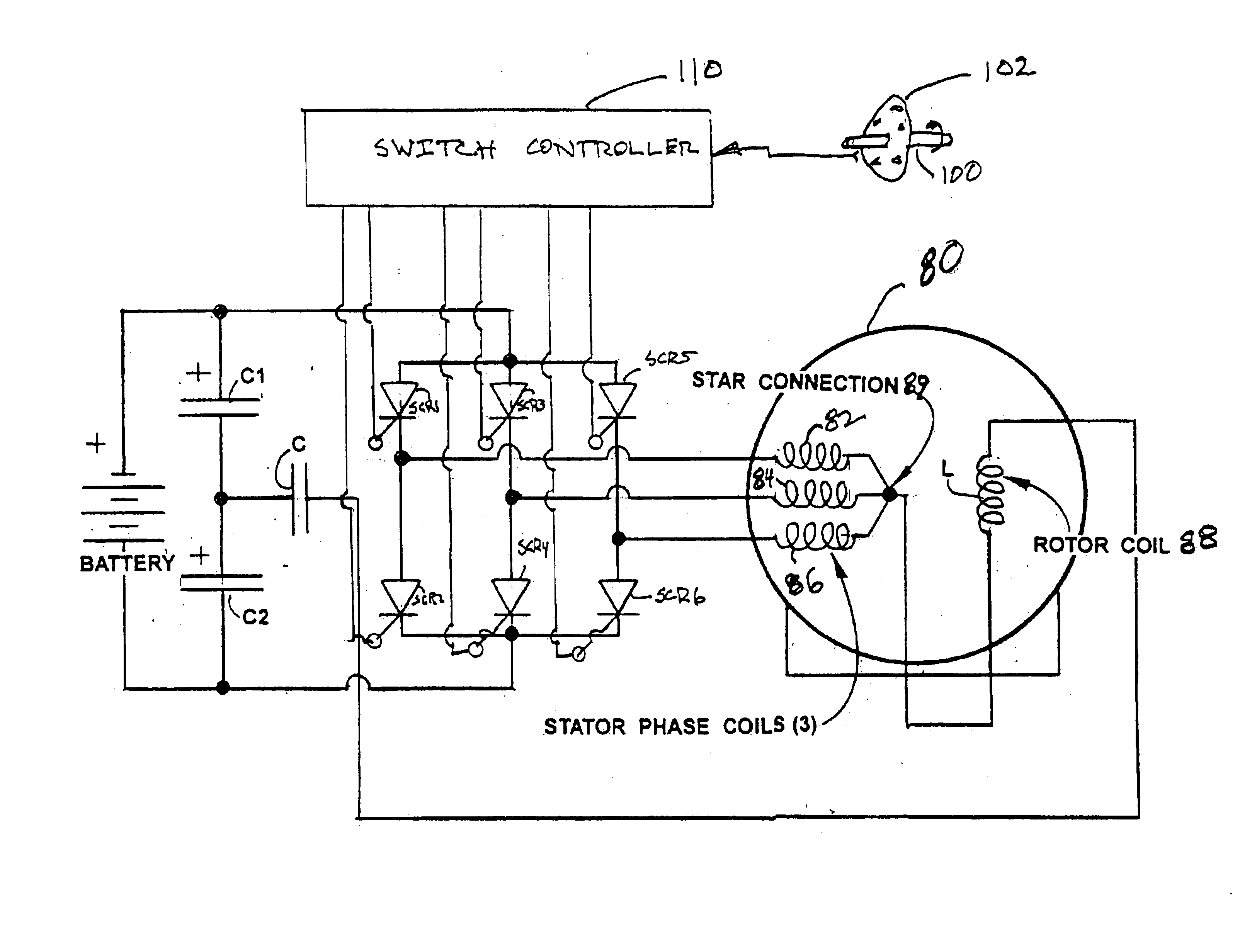
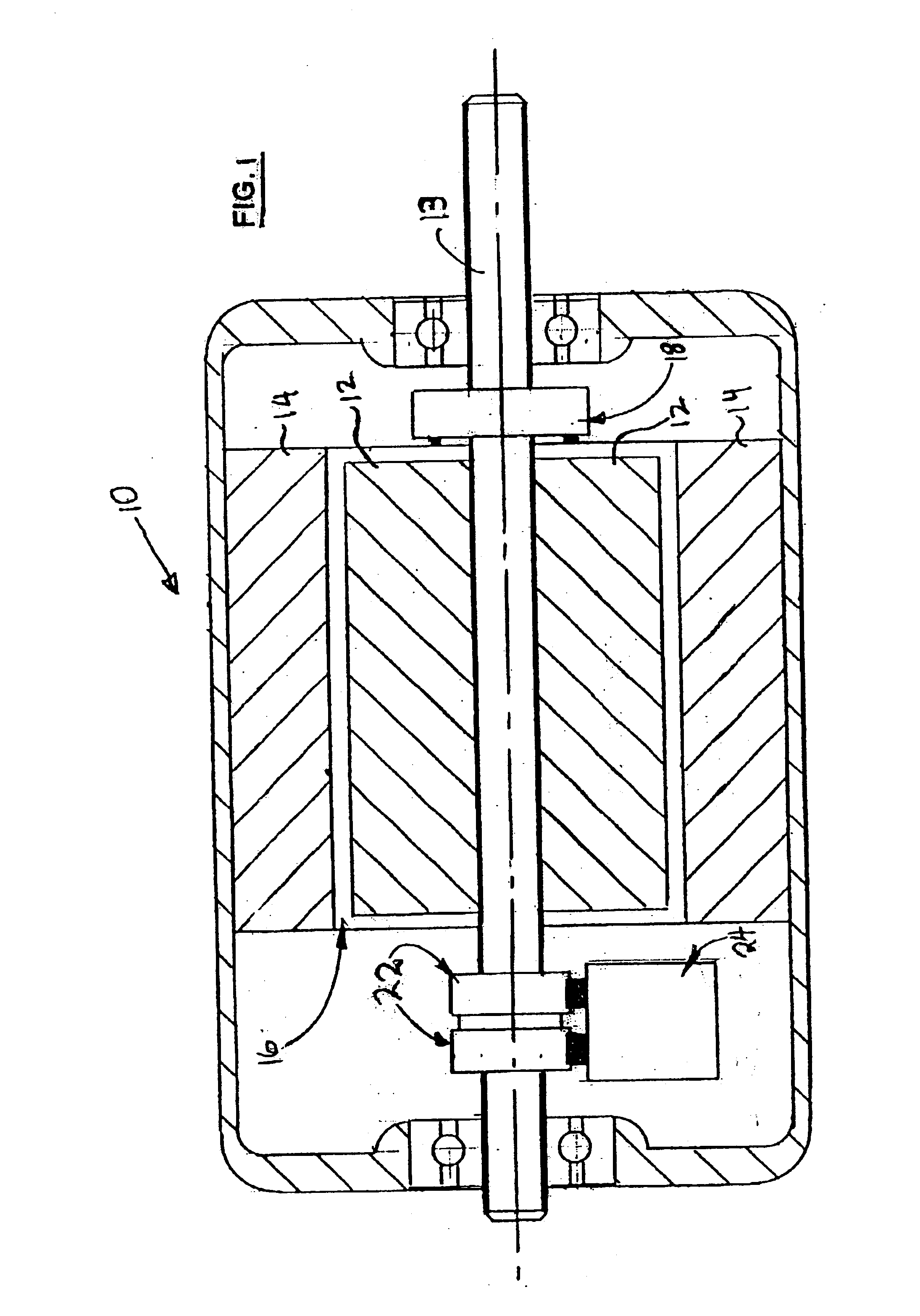
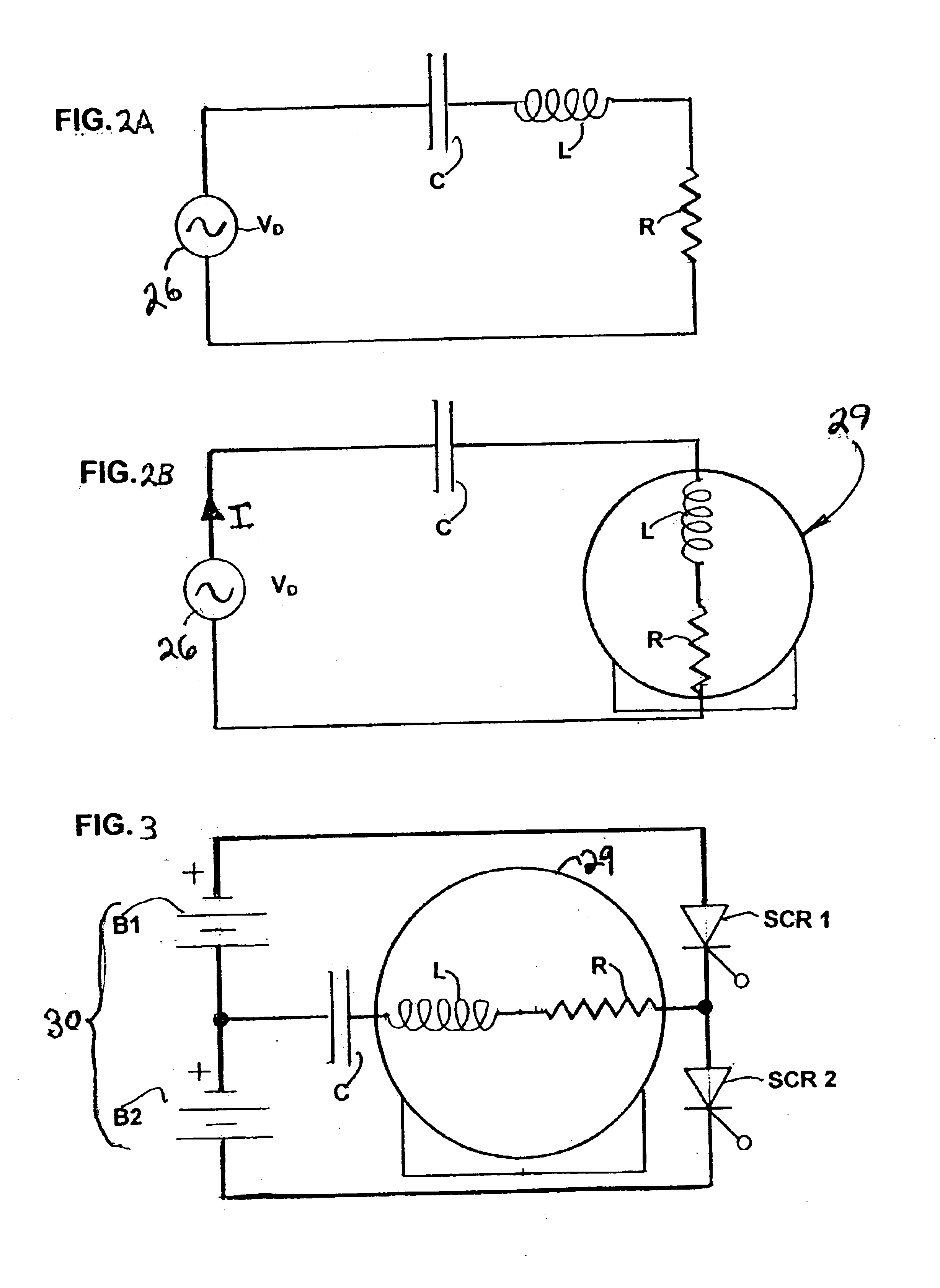
In this description, the term “resonant motor system” is used. In such a system, an electrical motor has a physical air gap between the stator and rotor of a size sufficient to store magnetic energy so that the motor's coils (also “windings”) in combination with the elements on which they are disposed and the air gap exhibit the electrical properties of an inductor, instead of the electrical properties of a transformer. When the inductance of the motor is connected in series with a capacitor, a resonant circuit results of which the motor itself constitutes the inductive element. The critical insight is that such a model enables the construction, deployment and operation of a compact, highly efficient, and inexpensive drive for exciting the motor.

Thus, contrary to conventional practice, this invention enhances and amplifies the inherent inductive properties of a motor's coil / iron structure by increasing the rotor-stator air gap. A capacitor external to the motor is connected in serie...


PUM


Abstract

In a resonant motor system, an electrical motor having a stator with one or more windings, a rotor which may or may not be wound, and an air gap between the stator and the rotor for storing magnetic energy such that the motor exhibits a definite electrical inductance may be deployed with a drive combination including a capacitance connected in series with the inductance of the motor to form an LCR circuit therewith. Phased provision of DC power to the LCR circuit causes the circuit to oscillate, which excites the motor. The DC power is provided in synchronism with the rotation of the rotor in order to maximize torque produced by the motor.

Description

FIELD OF THE INVENTIONThe invention is generally in the field of electrical motors. More particularly, the invention concerns an electrical motor caused to operate in response to one or more alternating electrical signals. The invention also relates to an electrical motor system in which an electrical motor is connected to form a resonant circuit with a drive capacitance through which is provided the excitation which causes the motor to operate.BACKGROUND OF THE INVENTIONElectrical motors are well known. Although there is a host of electrical motor designs, the standard 3-phase AC induction motor is the established workhorse of industry. In its essential aspects this electrical motor is a direct electromechanical analogue of the 3-phase generators utilized in power plants. In this regard, the 3-phase induction motor is a natural fit for the type of AC power available for its operation. When running directly from 3-phase AC grid power, no conceivable motor scheme is more adaptable or...

Claims


Application Information

Patent Timeline
Patent Type & Authority Patents(United States)
IPC IPC(8): H02K57/00H02P25/16H02K11/00
CPCH02P25/16H02K57/006H02K11/00H02P2201/05H02K11/0094H02K99/20
Inventor KERLIN, JACK H.
Owner PRATT & WHITNEY POWER SYST
Why Eureka
Try Eureka