Automatic gain control method and device

a gain control and automatic technology, applied in automatic tone/bandwidth control, amplifiers, semiconductor devices/discharge tubes, etc., can solve the problems of inability to generate an automatic gain control signal based on input signals, inability to carry out close loop control devices in response, and inability to detect the variation in input signal level, etc., to prevent the reduction of control voltage and good receiving characteristics

Inactive Publication Date: 2005-01-25
PANASONIC CORP
View PDF14 Cites 20 Cited by
  • Summary
  • Abstract
  • Description
  • Claims
  • Application Information

AI Technical Summary

Benefits of technology

The present invention has been made to overcome such subject in the prior art, and it is an object of the present invention to provide an excellent automatic gain control method and a device for embodying the same, which is able to execute always proper automatic gain control and also achieve good receiving characteristics by preventing reduction in a control voltage of a gain variable amplifying means when an S / N of the input signal is degraded, and a radio communication device with such automatic gain control function.

Problems solved by technology

Under such automatic gain control, if the S / N of the input signal is degraded and thus a level of the input signal is reduced below a level of the noise signal, it becomes impossible to detect the variation in the level of the input signal.
That is, it becomes impossible to generate an automatic gain control signal based on the input signal, so that the gain control of the variable amplifier at the preceding stage in the close loop control device cannot be carried out in answer to the variation of the input signal.
In other words, if the device is employed under the noisy surroundings like the case the mobile telephone, the radio paging device (pager), or the like, for example, is employed with the movement under the surroundings with the extremely high noise level (surroundings in which there are much ignition noises of the vehicle, much radiation noises of electronic devices, etc.), or if the input signal level (received electric field strength) is low, the proper automatic gain control for the input signal cannot be achieved.
In this case, there are such problems that good receiving characteristics cannot be assured and thus the received signal cannot be derived at a desired level.
In the above-mentioned prior art, there is the problem that, when an S / N of the input signal is degraded and thus a level of the input signal is reduced below a level of the noise signal, reduction in a control voltage of a gain variable amplifier is caused and therefore proper automatic gain control cannot be achieved.
That is, there is such a drawback that good receiving characteristics of the device cannot be achieved.

Method used


Image

  • Automatic gain control method and device
  • Automatic gain control method and device
  • Automatic gain control method and device

Examples


first embodiment

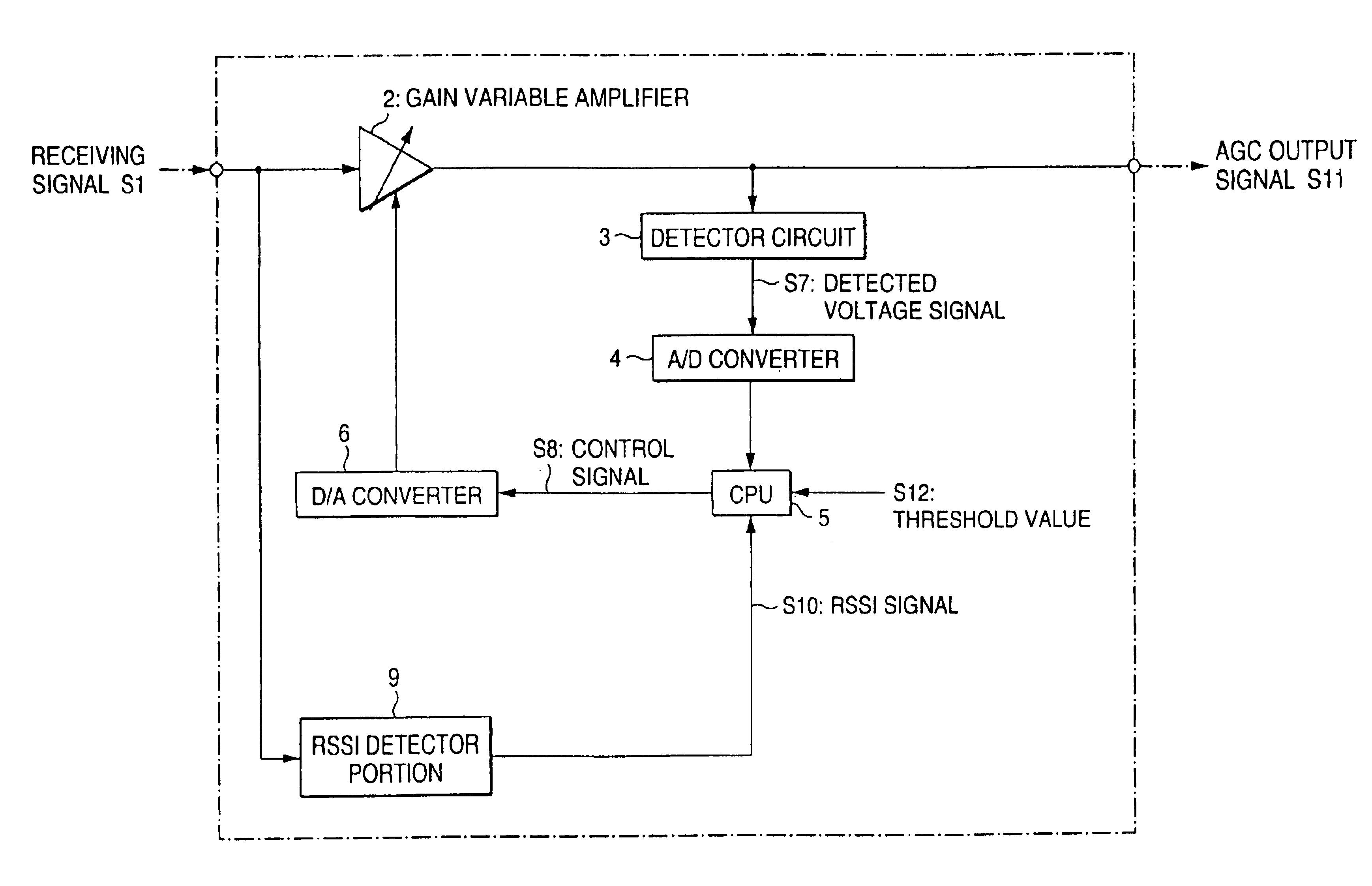
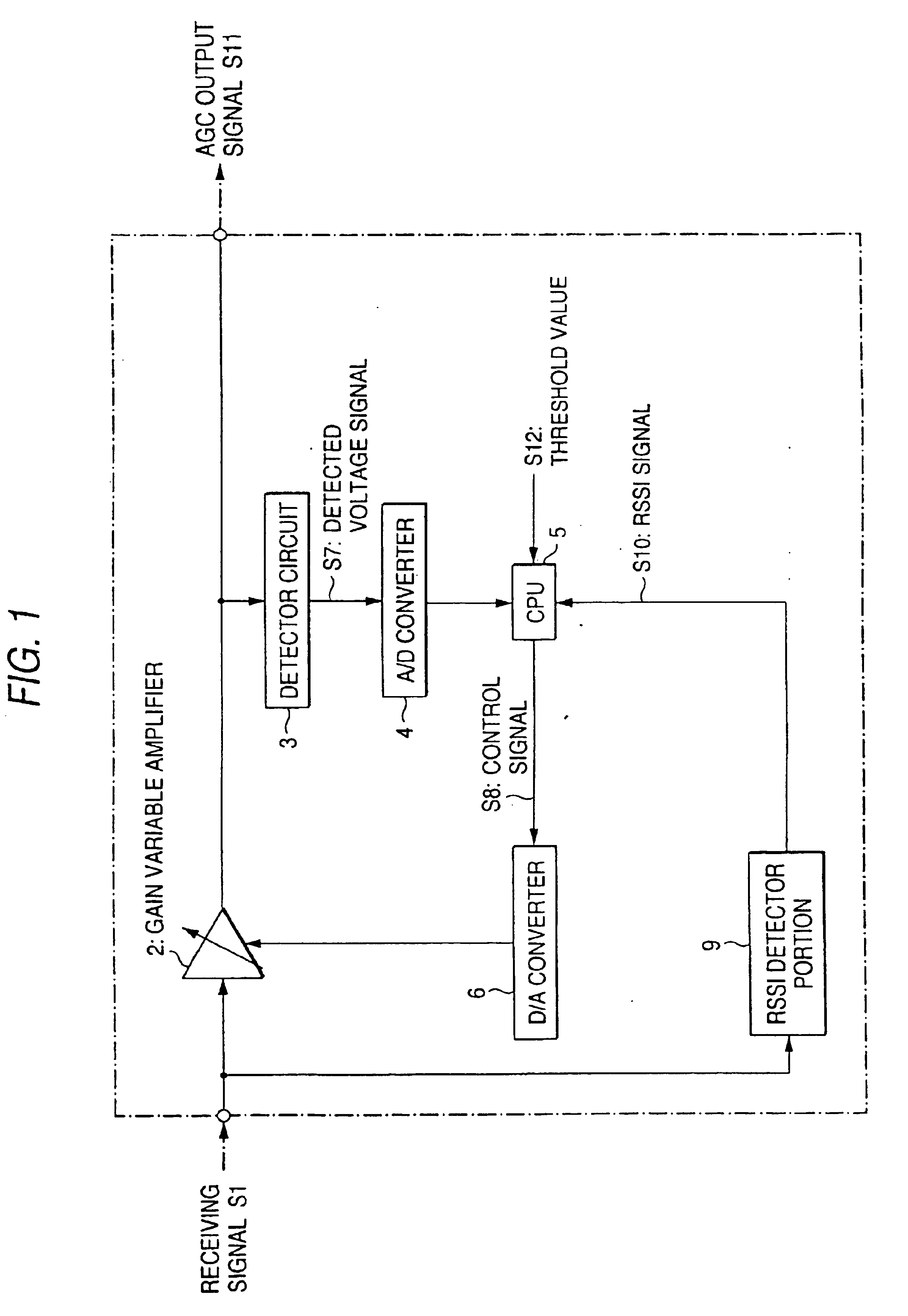
FIG. 1 is a block diagram showing an automatic gain control method and a configuration of a device for embodying the same according to a first embodiment of the present invention. In this disclosure, an example of a configuration of a digital automatic gain control device for executing the control in a digital fashion will be given hereunder.

The digital automatic gain control device is provided in a receiving system of a radio communication device such as the mobile telephone, the portable telephone, etc. Such digital automatic gain control device comprises a gain variable amplifier 2 for amplifying variably a receiving signal S1 (input signal) based on a control signal SB via the automatic gain control (AGC), then stabilizing a level of the signal, and then outputting the stabilized signal as an AGC output signal S11, and a detector circuit 3 serving as a detecting means which detects a level of the AGC output signal 11 output from the gain variable amplifier 2 to then output a det...

second embodiment

FIG. 4 is a block diagram showing a configuration according to a second embodiment of the present invention.

Like the above first embodiment, a digital automatic gain control device according to this second embodiment comprises the gain variable amplifier 2, the detector circuit 3, the A / D converter 4, the CPU 5, the D / A converter 6, and the RSSI detector portion 9. In addition, the second embodiment comprises a latch circuit 22 which corresponds to a control signal holding means which latches the control signal S8 generated by the CPU 5 and then outputting it as a preceding control signal S21 serving as the control signal stored at the time of preceding execution of the gain control, and a latch circuit 24 which corresponds to a signal level holding means which latches the RSSI signal S10 detected by the RSSI detector portion 9 and then outputting it as a preceding RSSI signal S23 which is the RSSI signal stored at the time of preceding execution of the gain control. In this case, b...

third embodiment

FIG. 5 is a block diagram showing a configuration according to a third embodiment of the present invention.

Like the foregoing first embodiment, a digital automatic gain control device according to this third embodiment comprises the gain variable amplifiers 2, the detector circuit 3, the A / D converter 4, the CPU 5, the D / A converter 6, and the RSSI detector portion 9. In addition, the third embodiment comprises a latch circuit 25 which corresponds to a detected voltage holding means which latches the detected voltage signal S7 generated by the detector circuit 3 as the digital signal and then outputting it as a preceding detected voltage signal S26 serving as the detected voltage signal stored at the time of preceding execution of the gain control, and the latch circuit 24, as employed in the second embodiment, for latching the RSSI signal S10 detected by the RSSI detector portion 9 and then outputting it as the preceding RSSI signal S23 which is the RSSI signal stored at the time o...


PUM


Abstract

A constant output signal can be achieved by controlling a gain variable amplifier 2 based on a level of an output signal which is derived by variably amplifying a receiving signal S1 (input signal). An AGC output signal S11 is detected by a detector circuit 3, then a detected voltage signal S7 is converted into a digital signal by an A/D converter 4 to output it to a CPU 5. Then, the CPU 5 generates a control signal S8 based on the detected voltage signal S7, then an A/D converter 6 converts the control signal S8 into the analogue signal, and then the signal is sent out to the gain variable amplifier 2 to execute gain control. At this time, an RSSI detector portion 9 detects an RSSI signal S10 corresponding to a transmitting signal level from the receiving signal S1, and then the CPU 5 sends out the control signal S8 stored at the time of preceding execution of the gain control when the RSSI signal S10 is reduced below a predetermined threshold value S12. In the weak received electric field strength, the control voltage for the gain variable amplifier is prevented reduction, and the proper automatic gain control can be made possible to thus achieve the good receiving characteristics.

Description

BACKGROUND OF THE INVENTIONThe present invention relates to automatic gain control (referred suitably to as “AGC” hereinafter) which is able to stabilize an input signal whose level is varied in a mobile communication device, etc. via gain control using a closed loop and then output it and, more particularly, an automatic gain control method and a device for embodying the same, which is able to execute the automatic gain control based on a transmission signal level (received signal strength indicator (RSSI) signal, etc.) detected from the input signal when a signal-to-noise (S / N) ratio of the input signal is degraded, and a radio communication device with such automatic gain control function.In the prior art, in various signal processing devices, e.g., in the radio communication device, the automatic gain control (AGC) which stabilizes variation in a signal level of the received signal caused due to variation in a received electric field strength on a radio wave propagation path suc...

Claims


Application Information

Patent Timeline
Patent Type & Authority Patents(United States)
IPC IPC(8): H03G3/20H03G3/30H03G5/16H04B1/18
CPCH03G3/30H03G3/3078H03G3/3052
Inventor IWATA, YASUSHIICHIKAWA, YASUFUMI
Owner PANASONIC CORP
Why Eureka
Try Eureka