Liquid crystal display device

Inactive Publication Date: 2005-01-25
SHARP KK
View PDF30 Cites 43 Cited by
  • Summary
  • Abstract
  • Description
  • Claims
  • Application Information

AI Technical Summary

Benefits of technology

Hereinafter, the effects of the present invention will be described.
In the LCD of the present invention, the thickness of the color filter layer in at least a part of the reflection region is smaller (thinner) than the thickness of the color filter layer in the transmission region. This suppresses reduction in transmittance in the reflection region and improves light utilization efficiency. Accordingly, display in the reflection region does not become dark even if the color filter layer is formed almost over the whole reflection region in order to provide display having high color purity in the reflection region. As a result, bright display having high color purity (excellent color reproduction) is implemented in both the transmission region and the reflection region.
In the case where the transparent dielectric layer is formed between the transparent substrate and the color filter substrate in at least a part of the reflection region, the material of the color filter layer has a reduced thickness on the transparent dielectric layer. Therefore, the thickness of the color filter layer on the transparent dielectric layer becomes smaller (thinner) than the thickness of the color filter layer in the region having no transparent dielectric layer. Accordingly, the color filter layer having the above thickness distribution can be easily obtained. Therefore, in the case where the transparent dielectric layer is formed between the transparent substrate and the color filter layer in at least a part of the reflection region, an LCD capable of implementing bright display with high color purity in both the transmission region and the reflection region can be manufactured by a simple manufacturing process.
In the case where a plurality of transparent dielectric layers are provided in each reflection region, a color filter layer having the above thickness distribution can be reliably obtained.
In the case

Problems solved by technology

As a result, the transmission-type LCD is capable of providing bright display having a high contrast ratio, but has large power consumption due to the backlight.
If the luminance of the backlight is increased in order to maintain the visibility, power consumption would further be increased.
Moreover, the disadvantage of the transmission-type LCD (reduced visibility in a very bright environment (e.g., outdoor

Method used


Image

  • Liquid crystal display device
  • Liquid crystal display device
  • Liquid crystal display device

Examples


Example

First Embodiment

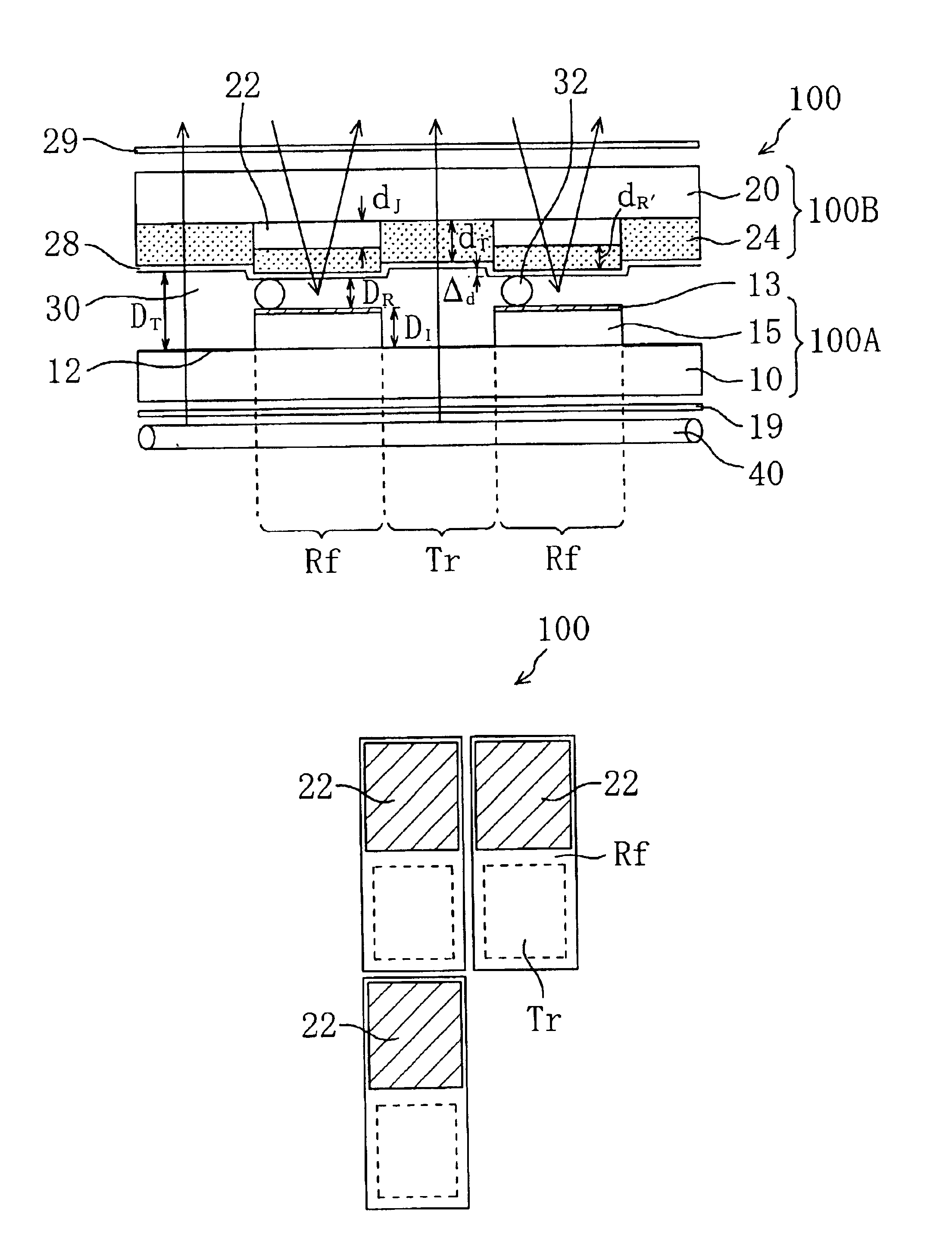
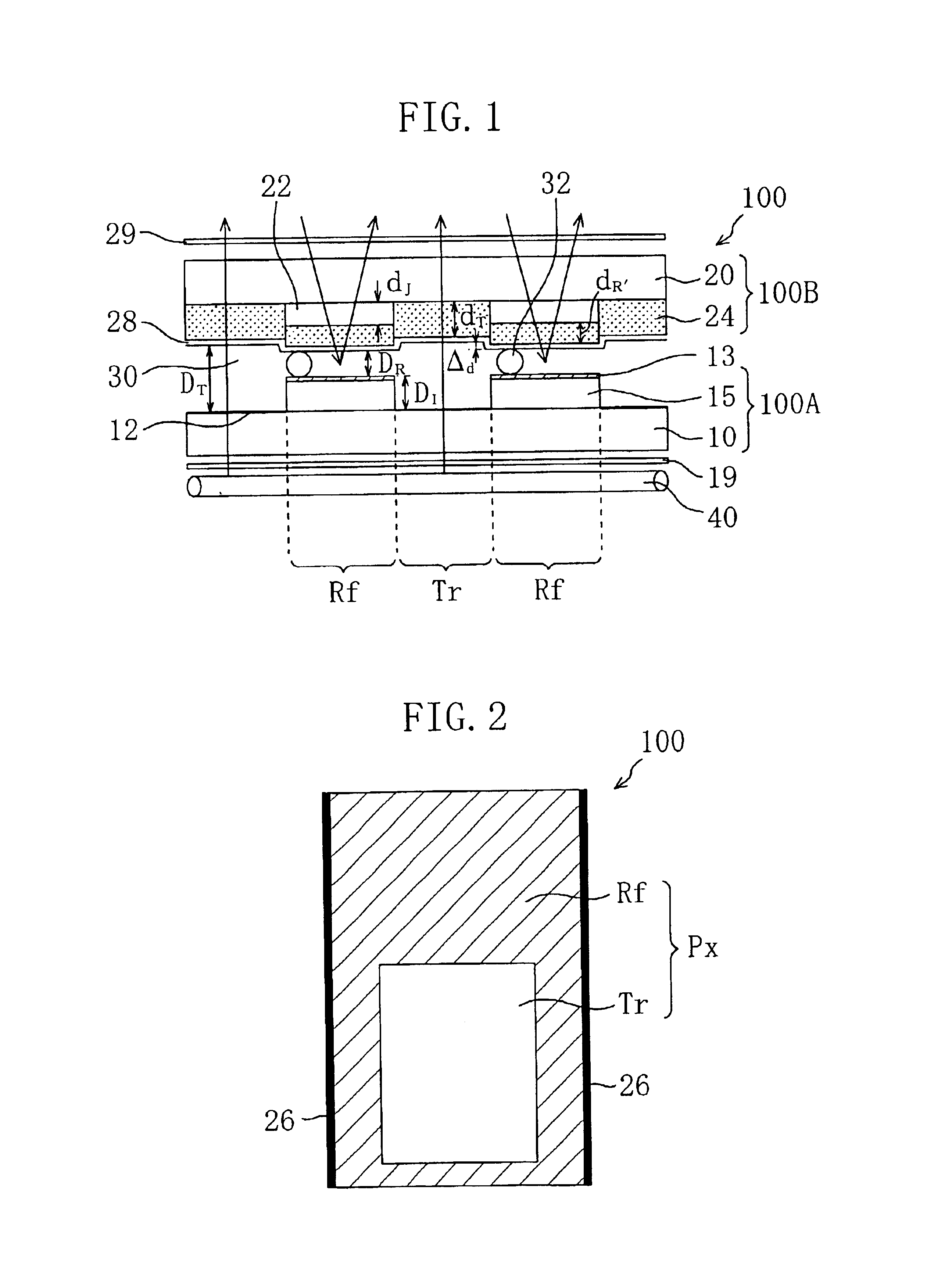
First, the structure of an LCD 100 according to the first embodiment of the present invention will be described with reference to FIGS. 1 and 2. FIG. 1 is a schematic cross-sectional view of the LCD 100. FIG. 2 is a schematic top view showing the structure of a single picture-element region in the LCD 100. In the specification, the minimum unit of display is referred to as “picture element”, and a region of the LCD which corresponds to a “picture element” is referred to as “picture-element region”.

As shown in FIG. 1, the LCD 100 includes an active matrix substrate (first substrate) 100A, a color filter substrate (second substrate) 100B, and a liquid crystal layer 30 interposed therebetween. Typically, the LCD 100 further includes a pair of polarizing plates 19, 29 and an illuminating device (backlight) 40. The pair of polarizing plates 19, 29 are provided on both sides of the LCD 100, and the illumination device (backlight)40 is provided outside the polarizing plate ...

Example

Second Embodiment

FIG. 12 schematically shows the cross-sectional structure of an LCD 200 according to the second embodiment of the present invention. The LCD 200 of the second embodiment is different from the LCD 100 of the first embodiment in the structure of an active matrix substrate 200A. In FIG. 12 and the following figures, components having substantially the same function as that of the components in the LCD 100 of the first embodiment are denoted with the same reference numerals and characters, and description thereof is omitted.

As shown in FIG. 12, in the LCD 200 of the second embodiment, the level of the surface of the active matrix substrate 200A which faces the liquid crystal layer 30 is substantially the same in both the transmission region Tr and the reflection region Rf.

Moreover, in the LCD 200, the level of the surface of a color filter substrate 200B which faces the liquid crystal layer 30 is higher in the reflection region Rf than in the transmission region Tr. Mor...

Example

Third Embodiment

FIG. 17 schematically shows the cross-sectional structure of an LCD 300 according to the third embodiment of the present invention. The LCD 300 of the third embodiment is different from the LCD 200 of the second embodiment in that the LCD 300 includes a transparent dielectric layer 22′ having a light-diffusing function. In FIG. 17, components having substantially the same function as that of the components of the LCD 200 of the second embodiment are denoted with the same reference numerals and characters, and description thereof is omitted.

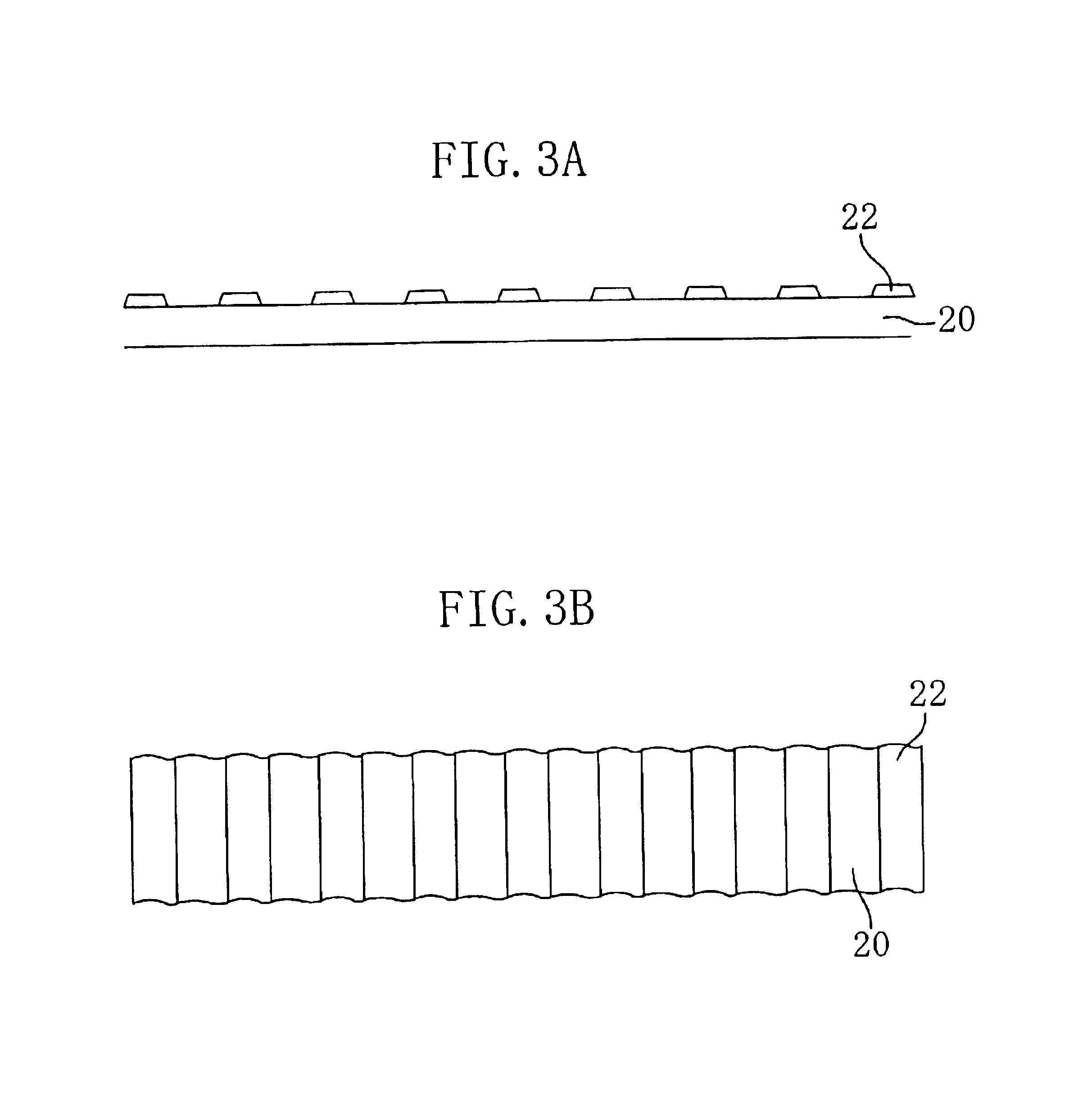
The color filter substrate 200B in the LCD 300 of the third embodiment includes a transparent dielectric layer 22′ having a light-diffusing function. Like the LCD 200 of the second embodiment, the transparent dielectric layer 22′ is formed in at least a part of the reflection region Rf.

Typically, the transparent dielectric layer 22′ having a light-diffusing function is formed from a transparent matrix material having a filler dispe...


PUM


Abstract

The liquid crystal display device includes a first substrate, a second substrate, a liquid crystal layer interposed between the first and second substrates, and a plurality of picture-element regions for providing display. Each of the plurality of picture-element regions has a transmission region for providing display in a transmission mode by using light incident through the first substrate, and a reflection region for providing display in a reflection mode by using light incident through the second substrate. The second substrate has a color filter layer provided in the transmission region and the reflection region. The thickness of the color filter layer in at least a part of the reflection region is smaller than the thickness of the color filter layer in the transmission region.

Description

BACKGROUND OF THE INVENTION1. Field of the InventionThe present invention generally relates to a liquid crystal display device (LCD). More particularly, the present invention relates to a transmission / reflection combination type LCD capable of providing display in transmission and reflection modes.2. Description of the Background ArtLiquid crystal display devices (LCDs) are thin, low power consumption display devices. Because of such characteristics, the LCDs are recently used in a variety of applications including office automation (OA) equipments such as word processors and personal computers, portable information equipments such as electronic organizers, and camera-incorporated VTRs (video tape recorders) having a liquid crystal monitor.These LCDs are roughly divided into two types: reflection type and transmission type. An LCD is not a self-light-emitting display device such as CRT (cathode ray tube) and EL (electroluminescence). In order to provide display, a transmission-type ...

Claims


Application Information

Patent Timeline
IPC IPC(8): G02F1/1335G02F1/13G02F1/1333
CPCG02F1/133555G02F1/133553G02F1/133371G02F1/133514G02F2203/09G02F1/1335
Inventor FUJIMORI, KOHICHINARUTAKI, YOZO
Owner SHARP KK
Why Eureka
Try Eureka