Current limiter for magneto-resistive circuit element

a current limiter and magnetoresistive circuit technology, applied in the field of circuits, can solve the problems of wasting power consumption, not knowing the number of means, and wasting unnecessary power, and achieve the effect of preventing catastrophic damag

Inactive Publication Date: 2005-01-25
AVAGO TECH WIRELESS IP SINGAPORE PTE +1
View PDF12 Cites 5 Cited by
  • Summary
  • Abstract
  • Description
  • Claims
  • Application Information

AI Technical Summary

Benefits of technology

And it is yet another object of the present invention to limit the current in a magneto-resistive element to a desired level so as to prevent catastrophic damage.

Problems solved by technology

Conventional approaches sometimes resort to fixed level limiting which wastes power consumption particularly when the bias current must be programmable over a wide range.
However, such apparatus is not known to include means for limiting the current to a level which can prevent catastrophic damage when the element is shorted.
Furthermore, limiting by means of shunting the excess current away requires large output devices and wastes unnecessary power.

Method used


Image

  • Current limiter for magneto-resistive circuit element
  • Current limiter for magneto-resistive circuit element
  • Current limiter for magneto-resistive circuit element

Examples


Embodiment Construction

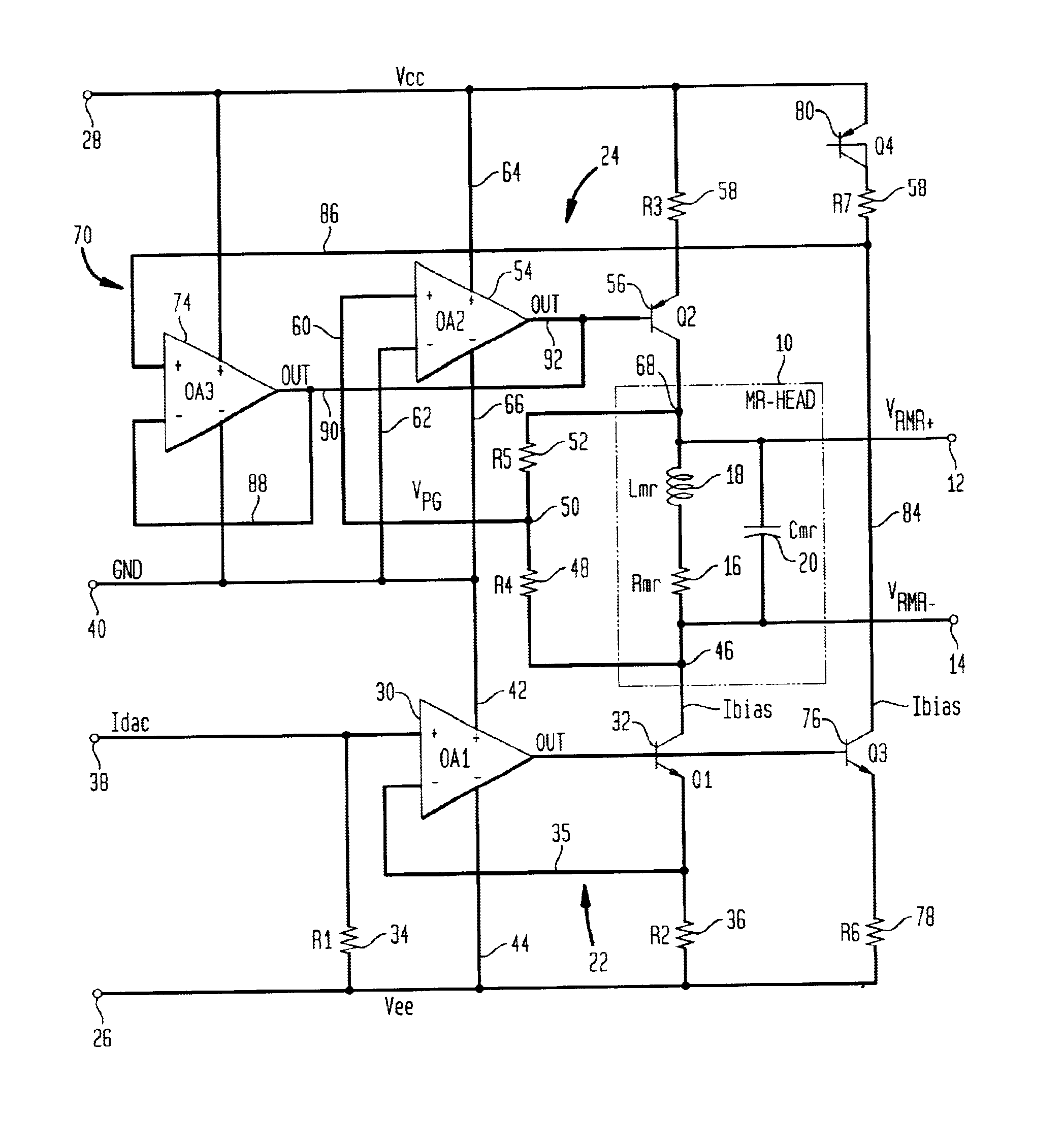
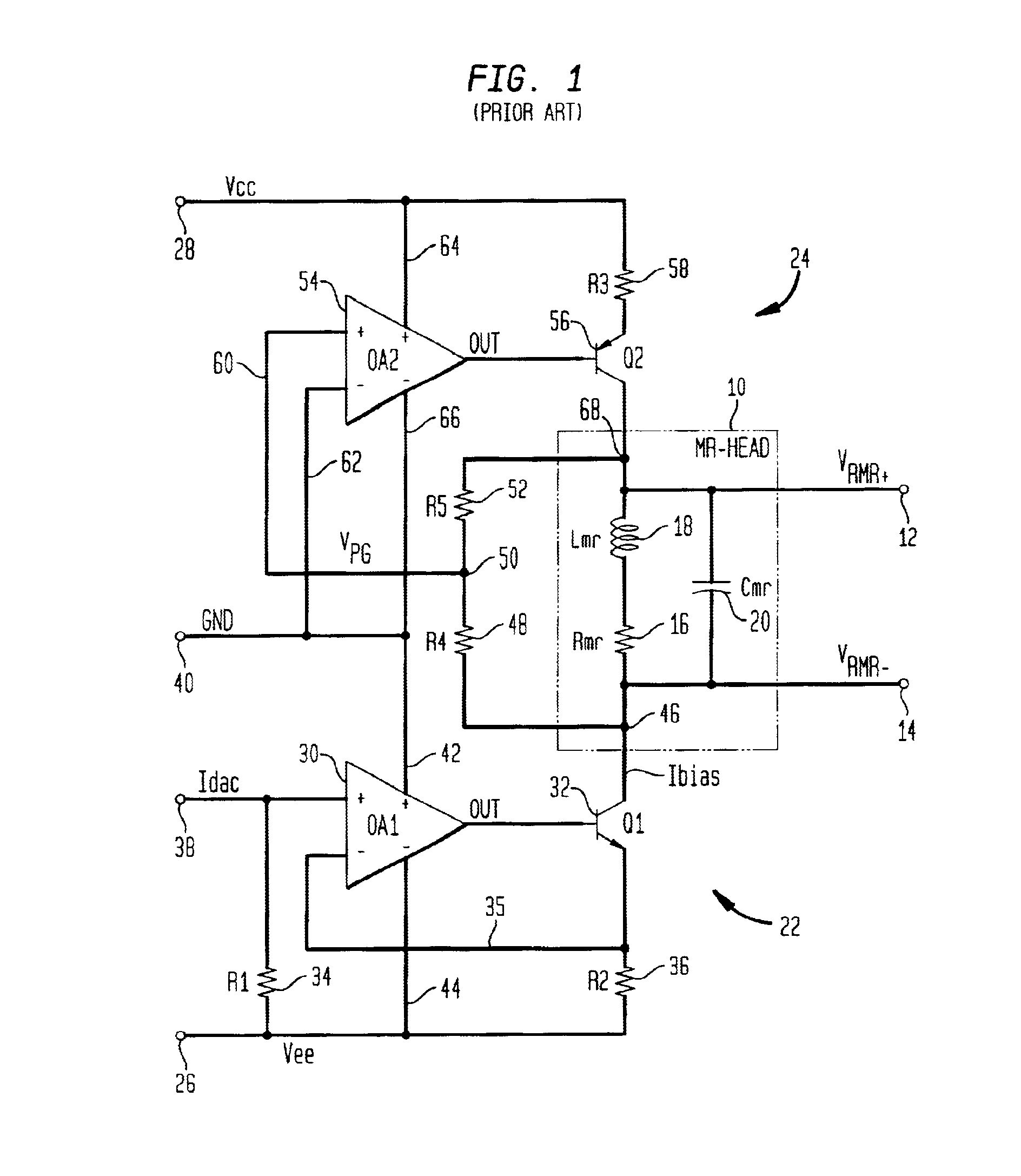
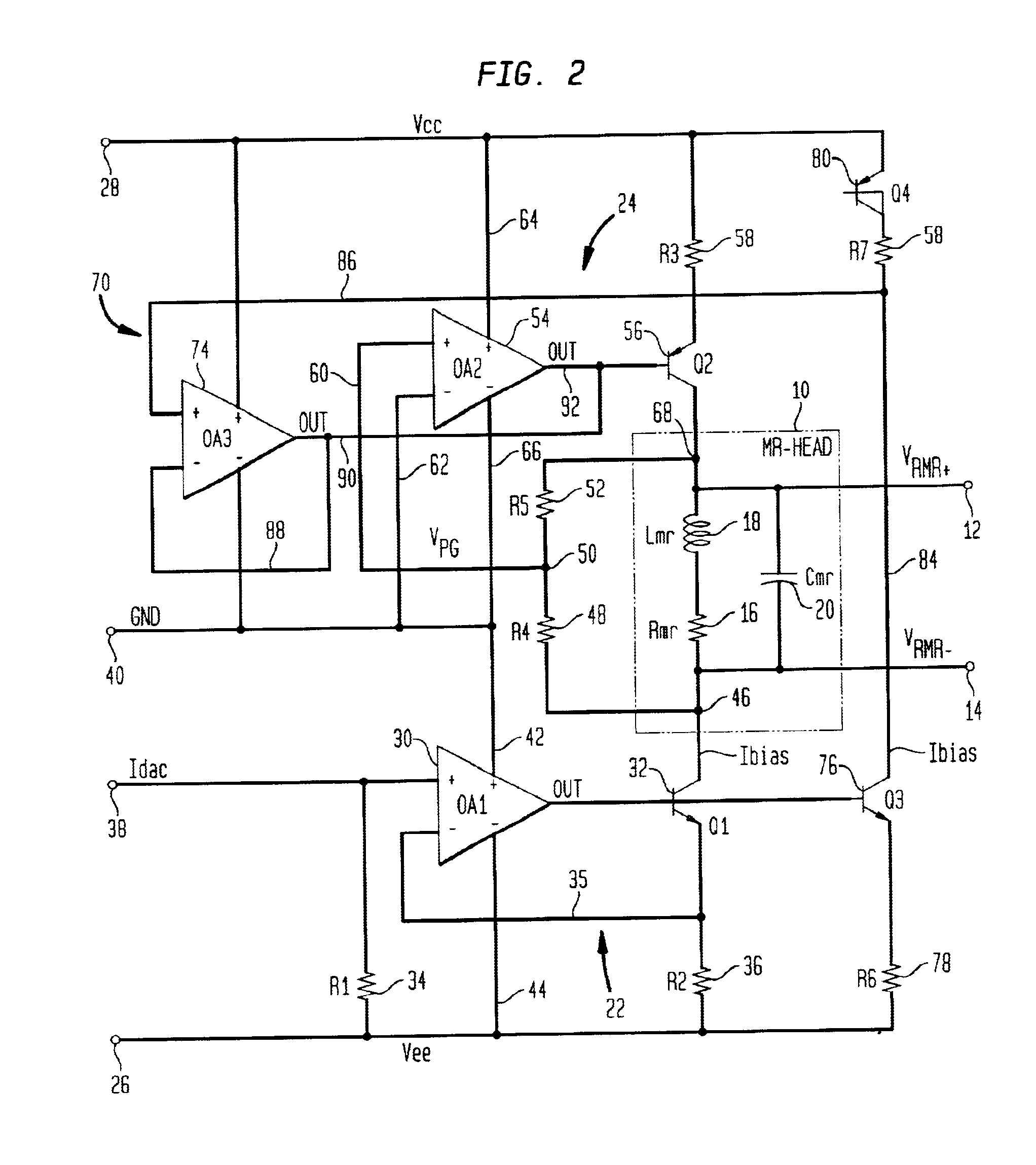
Referring now to the drawings wherein like reference numerals refer to like components throughout, attention is directed first to FIG. 1 wherein there is shown a schematic diagram of a conventional circuit for supplying and controlling bias current to a magneto-resistive read head (MR-HEAD) 10 which is connected to a high performance hard disk drive differential preamplifier, not shown, via differential voltage Vrmr+ and Vrmr− output terminals 12 and 14. The MR-HEAD 10 is comprised of resistive Rmr element 16, a series inductive Lmr element 18 and a parallel capacitive Cmr element 20. The lower and upper ends of the read head 10 are connected to servo loops 22 and 24 which have a Vee (−5 Vdc) supply voltage and Vcc (+5 Vdc) supply voltage coupled thereto via terminals 26 and 28.

The lower servo loop 22 includes an OA1 operational amplifier 30, an n-p-n bipolar transistor 32, an R1 resistor 34 and an R2 resistor 36. The (+) input terminal of OA130 is connected to an input terminal 38 ...


PUM

PropertyMeasurementUnit
currentaaaaaaaaaa
currentaaaaaaaaaa
output voltageaaaaaaaaaa

Abstract

A current limiter circuit for limiting current in an electrical circuit element such as the magneto-resistive portion of a read head forming a portion of a hard disk drive and including: a first circuit connected to one end of the circuit element for applying a bias current of a desired value to the circuit element in response to the value to an input signal; a second circuit connected to the other end of the circuit element for setting the amplitude of the voltage signal generated across the circuit element in response to the bias current; and a third electrical circuit connected to both the first and second circuits for limiting the value of bias current to a predetermined level for an abnormal event such as a current surge, a short circuit, or any other type of undesired current operating condition.

Description

BACKGROUND OF THE INVENTION1. Field of the InventionThis invention relates generally to circuitry for protecting an electrical circuit element from possible catastrophic damage during operation and more particularly to limiting circuitry for current in the magneto-resistive element of a magnetic read head in response to an abnormal operating condition such as a short circuit occurring in the element.2. Description of Related ArtApparatus for controlling the bias current in a magneto-resistive element utilized in a read head of a high performance hard disk drive differential preamplifier is generally known. Conventional approaches sometimes resort to fixed level limiting which wastes power consumption particularly when the bias current must be programmable over a wide range. However, such apparatus is not known to include means for limiting the current to a level which can prevent catastrophic damage when the element is shorted. Furthermore, limiting by means of shunting the excess c...

Claims


Application Information

Patent Timeline
Patent Type & Authority Patents(United States)
IPC IPC(8): G11B5/012G11B5/40G11B5/00G11B19/04
CPCG11B5/012G11B5/40G11B2005/0018G11B2005/0013G11B2005/0016G11B19/04
Inventor CLAPP, III, JOHN S.NGUYEN, THANH VAN
Owner AVAGO TECH WIRELESS IP SINGAPORE PTE
Why Eureka
Try Eureka