Shorting rings in dual-coil dual-gap loudspeaker drivers

a technology of shorting rings and loudspeaker drivers, applied in the direction of transducer details, electrical transducers, deaf-aid sets, etc., can solve the problem of not disclosing the use of shorting rings, and achieve the effect of reducing harmonic distortion and reducing the inductance of voice coils

Inactive Publication Date: 2005-01-25
HARMAN INT IND INC
View PDF16 Cites 21 Cited by
  • Summary
  • Abstract
  • Description
  • Claims
  • Application Information

AI Technical Summary

Benefits of technology

The shorting rings have no effect on a steady state magnetic field but act in opposition to any change in flux density or any displacement of the flux lines such a those that occur under the loading imposed when the voice coils are driven hard with audio frequency current. The location of the shorting rings determines their effect: location close to a voice coil reduces the voice coil inductance, location entirely within the magnetic flux loop centerline favors reduction of second harmonic and higher order even harmonic distortion, a centered location on the flux loop centerline, i.e. centered in the magnetic gap, favors reduction of third harmonic and higher order odd harmonic distortion, while location outside the flux loop centerline but near the voice coil acts to generally reduce harmonic distortion. Thus a plurality of rings can be differently located so as to optimally suppress both even and odd order harmonic distortion and reduce the voice coil inductance.

Problems solved by technology

Patents that disclose dual voice coil dual magnetic gap drivers / actuators include U.S. Pat. Nos. 4,612,592 to Frandsen, 5,231,336 to Van Namen, and French patent 1,180,456 to Kritter; however, these do not disclose the use of shorting rings.

Method used


Image

  • Shorting rings in dual-coil dual-gap loudspeaker drivers
  • Shorting rings in dual-coil dual-gap loudspeaker drivers
  • Shorting rings in dual-coil dual-gap loudspeaker drivers

Examples


Embodiment Construction

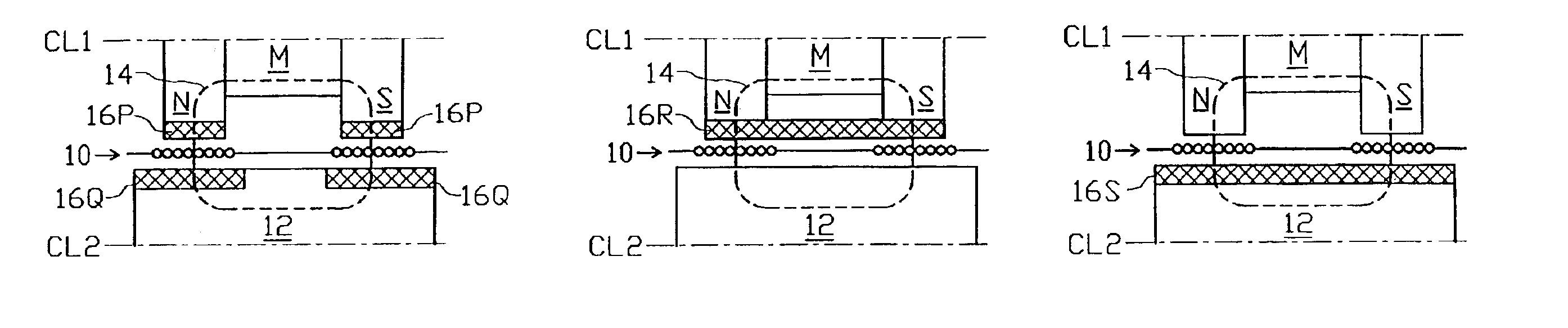
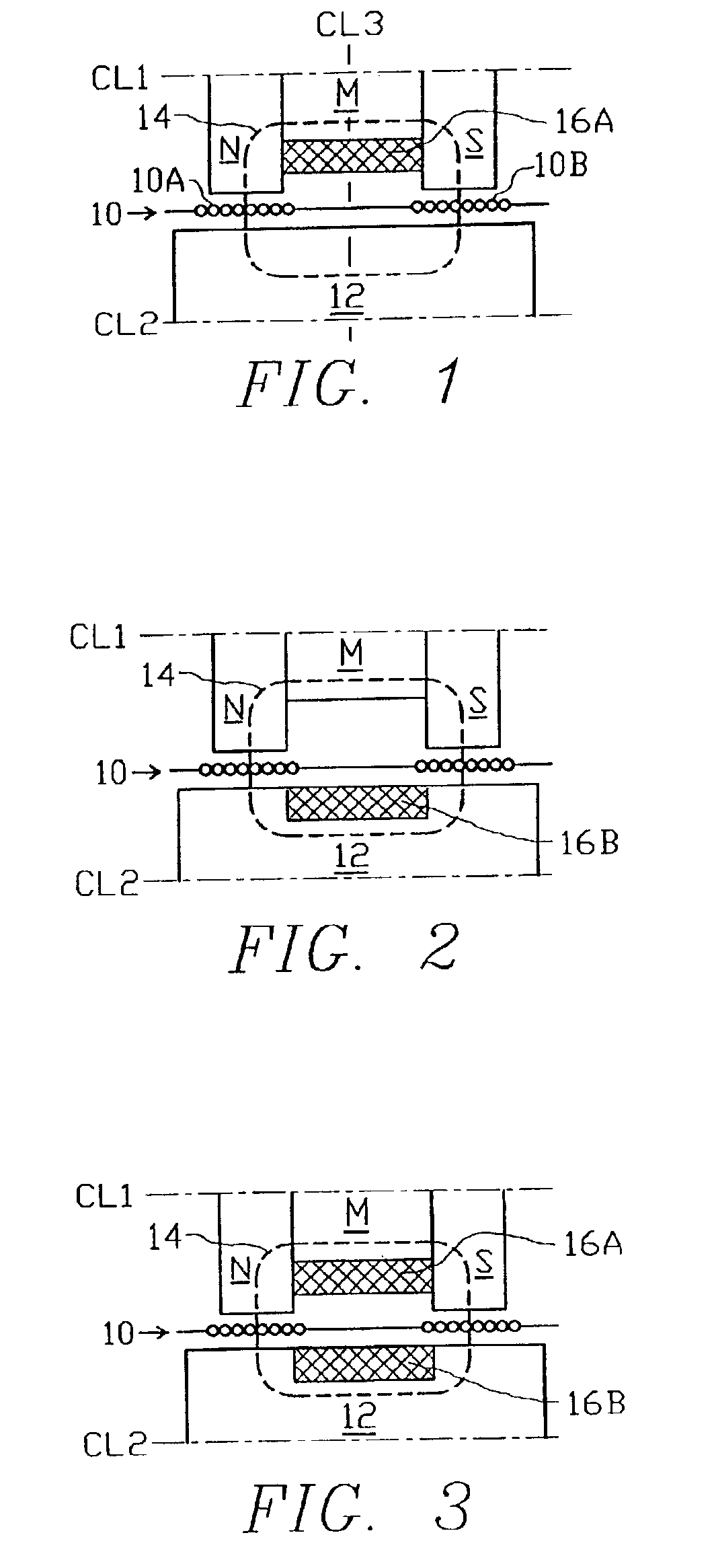
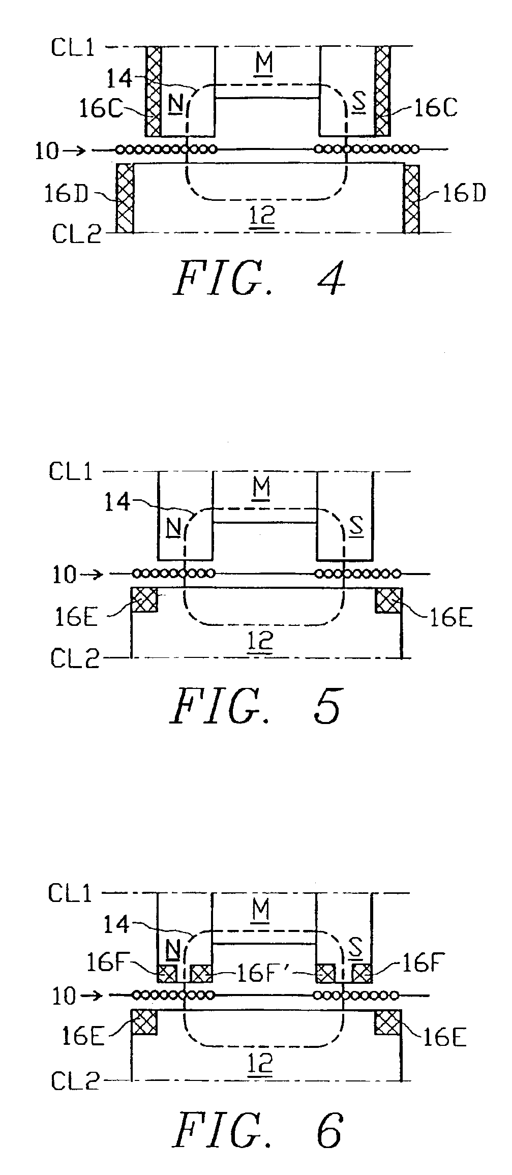
FIGS. 1-12 are basic functional representations of a dual-gap dual-voice-coil loudspeaker driver, shown in half cross-section with a voice coil assembly 10 carrying voice coils 10A and 10B suspended in a pair of magnetized air gaps formed from a permanent magnet M disposed between a first steel pole N, at the north poles of magnet M, and a second steel pole S at the south end of magnet M, and a yoke 12 which is made of magnetic material and which can be considered to define, in effect, a pair of pole faces that would substantially mirror the articulated pole pieces N and S of magnet M and thus form the two magnetic gaps.

The magnetic system of the foregoing structure sets up a magnetic flux loop in the path shown as a dashed line, i.e. flux loop center line 14, which is typically centered within each magnetic gap and within each voice coil 10A and 10B.

Voice coil assembly 10 is constrained by well known spring suspension diaphragm structure (not shown) so that it travels axially, typi...


PUM


Abstract

Loudspeaker and other transducers of the dual-voice-coil/dual-magnetic-gap type can be improved by the addition of one or more annular shorting rings strategically located in the vicinity of the two magnetic gaps. The shorting rings have no effect on a steady state magnetic field but act in opposition to any change in flux density or any displacement of the flux lines such as those that occur under the loading imposed when the voice coils are driven hard with audio frequency current. The location of the shorting rings determines their effect: location close to a voice coil reduces the voice coil inductance, location entirely within the magnetic flux loop centerline favors reduction of second harmonic distortion and higher order even harmonic distortion, a centered location on the flux loop centerline, i.e. centered in the magnetic gap, favors reduction of third harmonic and higher odd order harmonic distortion, while location outside the flux loop as defined by its center line but near the voice coil acts to generally reduce harmonic distortion and reduce the voice coil inductance. Thus a plurality of rings can be strategically deployed at different locations so as to optimally suppress both even and odd order harmonic distortion and to reduce the voice coil inductance.

Description

FIELD OF THE INVENTIONThe present invention relates to the field of electromagnetic transducers and actuators, and more particularly it relates to improvements in loudspeaker drivers of the type having dual voice coils axially located in corresponding dual annular magnetic air gaps on a common axis.BACKGROUND OF THE INVENTIONIn addressing fundamental design issues of dual-voice-coil dual magnetic-gap loudspeaker drivers as related to conventional single-voice-coil drivers, the present inventors have found that the dual-voice-coil dual-gap type offers advantages with regard to linearity, efficiency, available voice coil excursion, power compression, heat dissipation and maximum sound pressure output capability. Furthermore, they have found that certain benefits of the dual-coil dual gap approach can be further enhanced by introducing shorting rings in the region of the two magnetic gaps near the voice coils.DISCUSSION OF RELATED KNOW ARTJapanese patent 61-137496 to Okada introduces a...

Claims


Application Information

Patent Timeline
Patent Type & Authority Patents(United States)
IPC IPC(8): H04R9/00H04R9/06
CPCH04R9/063H04R2209/041
Inventor BUTTON, DOUGLAS J.HYDE, RALPH E.SALVATTI, ALEX V.
Owner HARMAN INT IND INC
Why Eureka
Try Eureka