Heat treatment apparatus and method of heat treatment

a heat treatment apparatus and heat treatment technology, applied in lighting and heating apparatus, drying machines with progressive movements, furnaces, etc., can solve the problems of reducing the reliability of exhaust treatment, affecting the yield of semiconductor chips or lcd, and the efficiency of exhaust treatment being sometimes lowered, so as to facilitate periodic maintenance, improve the yield of products, and improve the reliability of products

Inactive Publication Date: 2005-02-01
SONY CORP
View PDF3 Cites 8 Cited by
  • Summary
  • Abstract
  • Description
  • Claims
  • Application Information

AI Technical Summary

Benefits of technology

An object of the present invention is to provide a heat treatment apparatus and method of heat treatment able to prevent an object to be heat-treated from causing the quality defects and thereby improve the yield of the product and to improve the reliability of the product even in a case where the sublimating components produced due to heat treatment become solids and drop down. Another object of the present invention is to provide a heat treatment apparatus and method of heat treatment able to facilitate the periodic maintenance and raise the production efficiency.

Problems solved by technology

For this reason, they sometimes becomes a cause of a drop in the yield of the semiconductor chips (or LCD) or a drop in the reliability.
As a result, the exhaust duct and the exhaust treatment apparatus become fouled, and the exhaust treatment efficiency was sometimes lowered.
However, this work is troublesome, so is not easy, and further the heat treatment apparatus had to be stopped during the work, so the production efficiency was sometimes lowered.
Further, in the latter material design of the photoresist film, while reduction of the sublimating components was possible, it was difficult to completely eliminate them.
In this way, periodic maintenance was indispensable, so a drop in the production efficiency occurred.
Various inventions have been proposed with respect to these disadvantages (for example, Japanese Unexamined Patent Publication (Kokai) No. 2000-173883), but none were sufficient.
For example, in the photolithography of semiconductor chips or LCDs, when the wafer or substrate on which the coating solution containing the photoresist film components was coated was heat treated, after the sublimating components produced due to the heat treatment became solids, the solids sometimes dropped down to the wafer causing defects in pattern formation.
Further, a drop in the yield of the semiconductor chips or LCDs and a decline in the reliability sometimes occurred.
To prevent the sublimating components from falling to the wafer or substrate, periodic maintenance of the heat treatment apparatus became necessary resulting in a drop in the production efficiency.

Method used


Image

  • Heat treatment apparatus and method of heat treatment
  • Heat treatment apparatus and method of heat treatment
  • Heat treatment apparatus and method of heat treatment

Examples


first embodiment

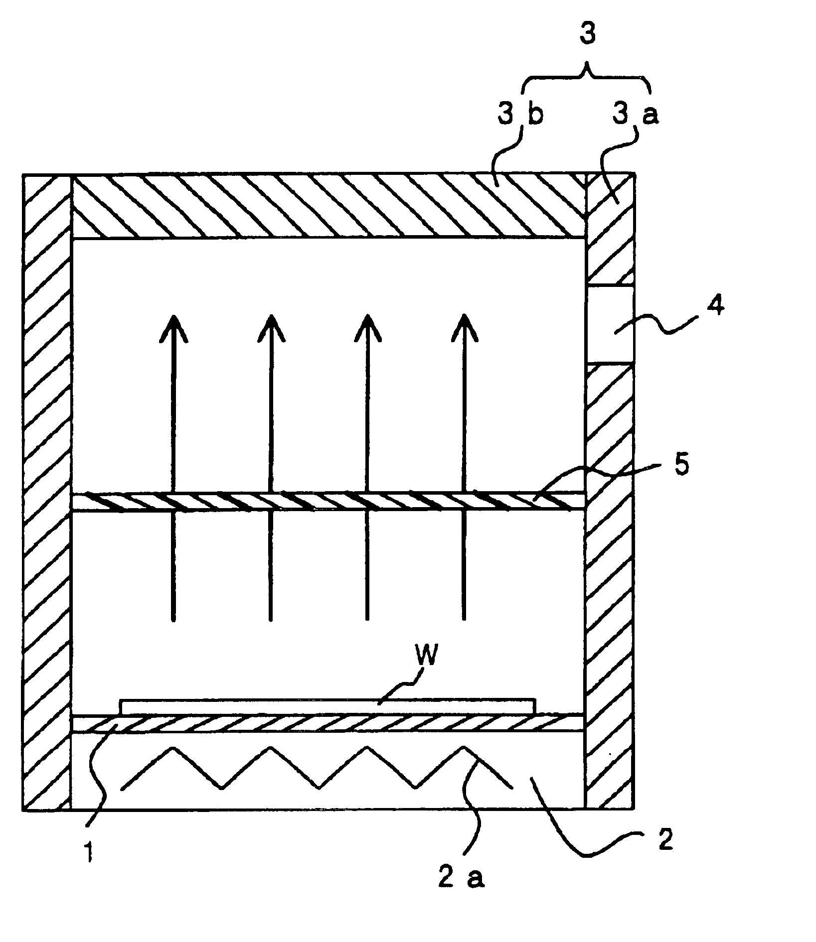
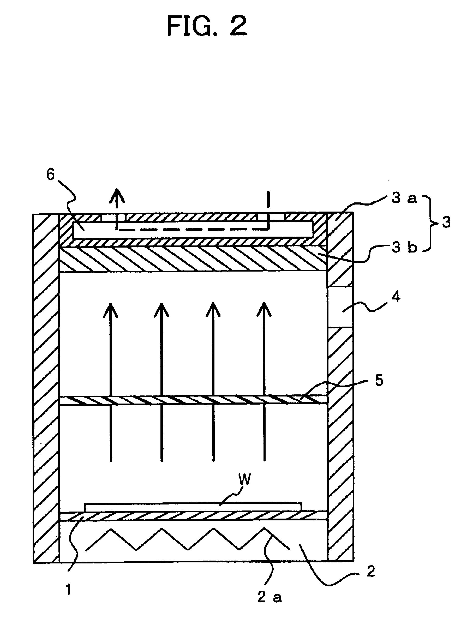
FIG. 1 is a schematic vertical sectional view of a heat treatment apparatus according to a first embodiment of the present invention. The heat treatment apparatus according to the first embodiment is provided with a stage 1, a heating unit 2, a cover portion 3, an exhaust port 4, and a trap 5. Here, the stage 1 places a wafer W or other heated object coated with a coating solution. Further, the heating unit 2 has a heater 2a for heating the object placed on the stage 1 and the coating solution from below. The cover portion 3 has a body 3a provided at the surrounding sides of the stage 1 and a top plate 3b for closing the upper opening of the body 3a and covers the object placed on the stage 1. The trap 5 is provided inside the cover portion 3 between the stage 1 and the top plate 3b, passes the gas generated from the coating solution due to the heating of the object, and traps the solids formed by the gas solidifying after passage and dropping down. The exhaust port 4 is provided in...

second embodiment

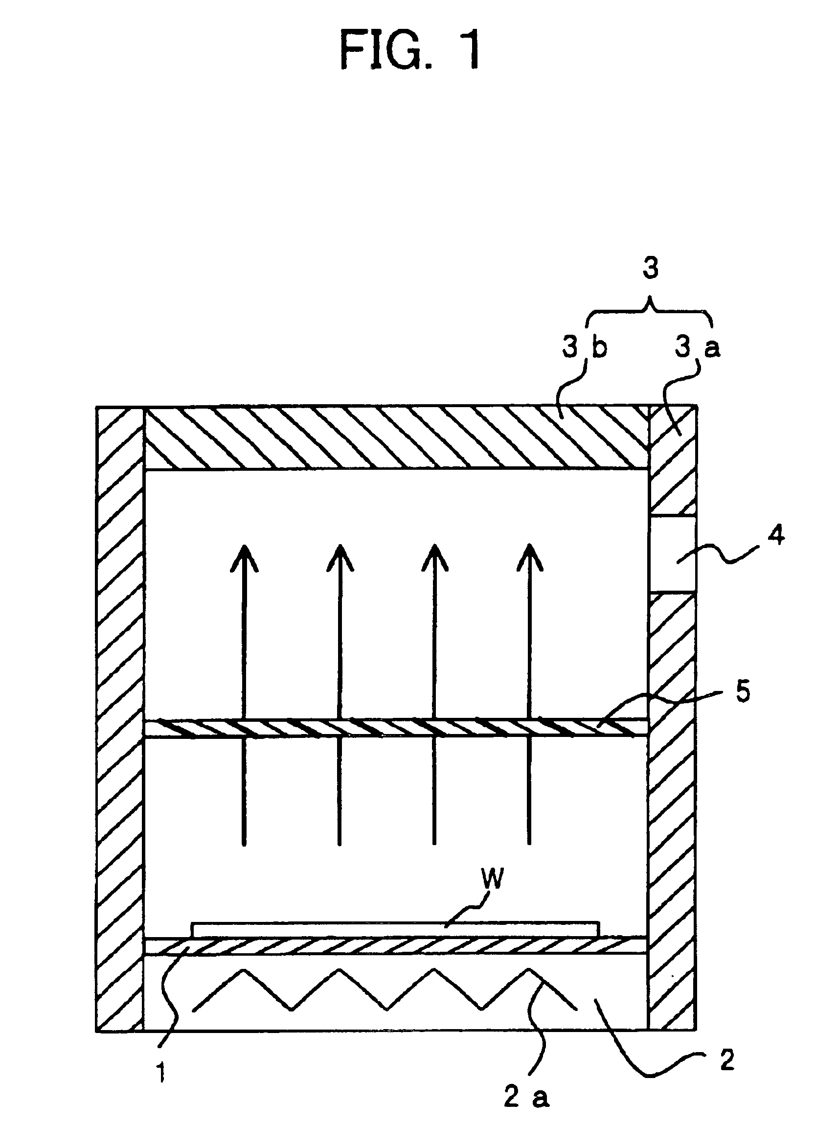
Next, an explanation will be given of a heat treatment apparatus according to a second embodiment of the present invention. FIG. 2 is a schematic vertical sectional view of the heat treatment apparatus according to the second embodiment. Portions common with those of the first embodiment explained above are given the same reference numerals, and explanations thereof are omitted.

The heat treatment apparatus according to the second embodiment is provided with a stage 1, a heating unit 2, a cover portion 3, an exhaust port 4, a trap 5, and a cooling unit 6. The cooling unit 6 is formed at the top plate 3b of the cover portion 3. Except for the fact that the cooling unit 6 is provided at the top plate 3b, this embodiment is the same as the first embodiment. Note that the stage 1, the heating unit 2, the cover portion 3, the exhaust port 4, the trap 5, and the cooling unit 6 in the present embodiment correspond to the stage, the heating unit, the cover, the exhaust port, the trap, and th...

third embodiment

Next, an explanation will be given of a heat treatment apparatus according to a third embodiment of the present invention. FIG. 3 is a schematic vertical sectional view of the heat treatment apparatus according to the third embodiment. Portions common with those of the first embodiment explained above are given the same reference numerals and explanations thereof are omitted.

The heat treatment apparatus according to the third embodiment is provided with a stage 1, a heating unit 2, a cover portion 3, an exhaust port 4, a trap 5, and a protective part 7. Except for the provision of the protective part 7, this embodiment is the same as the first embodiment. Note that the stage 1, the heating unit 2, the cover portion 3, the exhaust port 4, the trap 5, and the protective part 7 in the present embodiment correspond to the stage, the heating unit, the cover, the exhaust port, the trap, and the protective part in the present invention.

The components will be explained in detail below. The ...


PUM

PropertyMeasurementUnit
temperatureaaaaaaaaaa
thicknessaaaaaaaaaa
thicknessaaaaaaaaaa

Abstract

A heat treatment apparatus for preventing quality defects of an object to be heat-treated even when sublimating components produced in heat treatment become solids and drop down in the heat treatment apparatus, wherein a gas generated when heating an object to be heat-treated, coated with a coating solution and placed on a stage is passed through a trap made of a permeable porous film and is exhausted from an exhaust port of a cover and wherein solids produced and dropping down when gas passed through the trap of the permeable porous film solidifies at a top plate of the cover are trapped by the trap.

Description

RELATED APPLICATION DATAThe present application claims priority to Japanese Application(s) No(s). P2002-359661 filed Dec. 11, 2003, which application(s) is / are incorporated herein by reference to the extent permitted by law.BACKGROUND OF THE INVENTION1. Field of the InventionThe present invention relates to a heat treatment apparatus and a method of heat treatment, more particularly relates to a heat treatment apparatus in the process of production of semiconductor chips or liquid crystal display (LCD).2. Description of the Related ArtIn the process of production of semiconductor chips, an LCD, etc., a wafer or substrate is given desired patterns by utilizing photolithography for removing unnecessary portions. In photolithography, the unnecessary portions other than the desired patterns are generally removed by etching using a chemical. On the other hand, the required portions are protected by a photoresist, so remain even after the etching and thereby can give the desired patterns....

Claims


Application Information

Patent Timeline
Patent Type & Authority Patents(United States)
IPC IPC(8): H01L21/00H01L21/027H01L21/324
CPCH01L21/67103H01L21/67017H01L21/324
Inventor YAMAGUCHI, YUKO
Owner SONY CORP
Why Eureka
Try Eureka