Method of monitoring heat flux and controlling corrosion of furnace wall tubes

Active Publication Date: 2005-02-01
MISSISSIPPI LIME CO
View PDF11 Cites 22 Cited by
  • Summary
  • Abstract
  • Description
  • Claims
  • Application Information

AI Technical Summary

Benefits of technology

We provide method of measuring heat flux and resultant corrosion in a furnace of the type having a wall containing a plurality of tubes in which adjacent pairs of tubes are connected by a web or are welded together with the weld bead forming the web. We place a first thermocouple on a back side of one or more tubes which back side is not exposed to heat and products of combustion. A second thermocouple is attached to the back side of a web attached to that tube. We then measure a first heat flux temperature on the back side of the selected tube. We also measure a second heat flux temperature on the back side of the web adjacent to the selected tube. Next, we determine a difference between the first heat flux temperature and the second heat flux tempe

Problems solved by technology

Consequently, there is no access to the interior of most furnaces during most of the year.
If the ash remains solid in contact with the wall, it may accumulate, thus effectively insulating the water wall from its heat source and defeating the purpose or efficiency of the boiler.
If it melts on the wall, the liquid ash may cause corrosion.
However, the introduction of low NOx burners has increased the rate of corrosion of these tubes, which can reduce their life expectancy.
The result is that not only do tubes have to be replaced, but the corrosion problem has also resulted in the need to improve coal quality, or ash fusion characteristics, sometimes doubling the cost of coal.
Because the water inside tubes is at a high pressure, the tubes could fail if their walls become too thin as a result of corrosion.
While the industry has been able to determine corrosion rates from periodic measurements of wall thickness, corrosion rates determined in this way are of little use in efforts to control corrosion.
That is so because the measurement intervals are such that significant corrosion has occurred between measurements and further this significant corrosion does not shed light on the variation of conditions, mechanisms, coal properti

Method used


Image

  • Method of monitoring heat flux and controlling corrosion of furnace wall tubes
  • Method of monitoring heat flux and controlling corrosion of furnace wall tubes
  • Method of monitoring heat flux and controlling corrosion of furnace wall tubes

Examples


Embodiment Construction

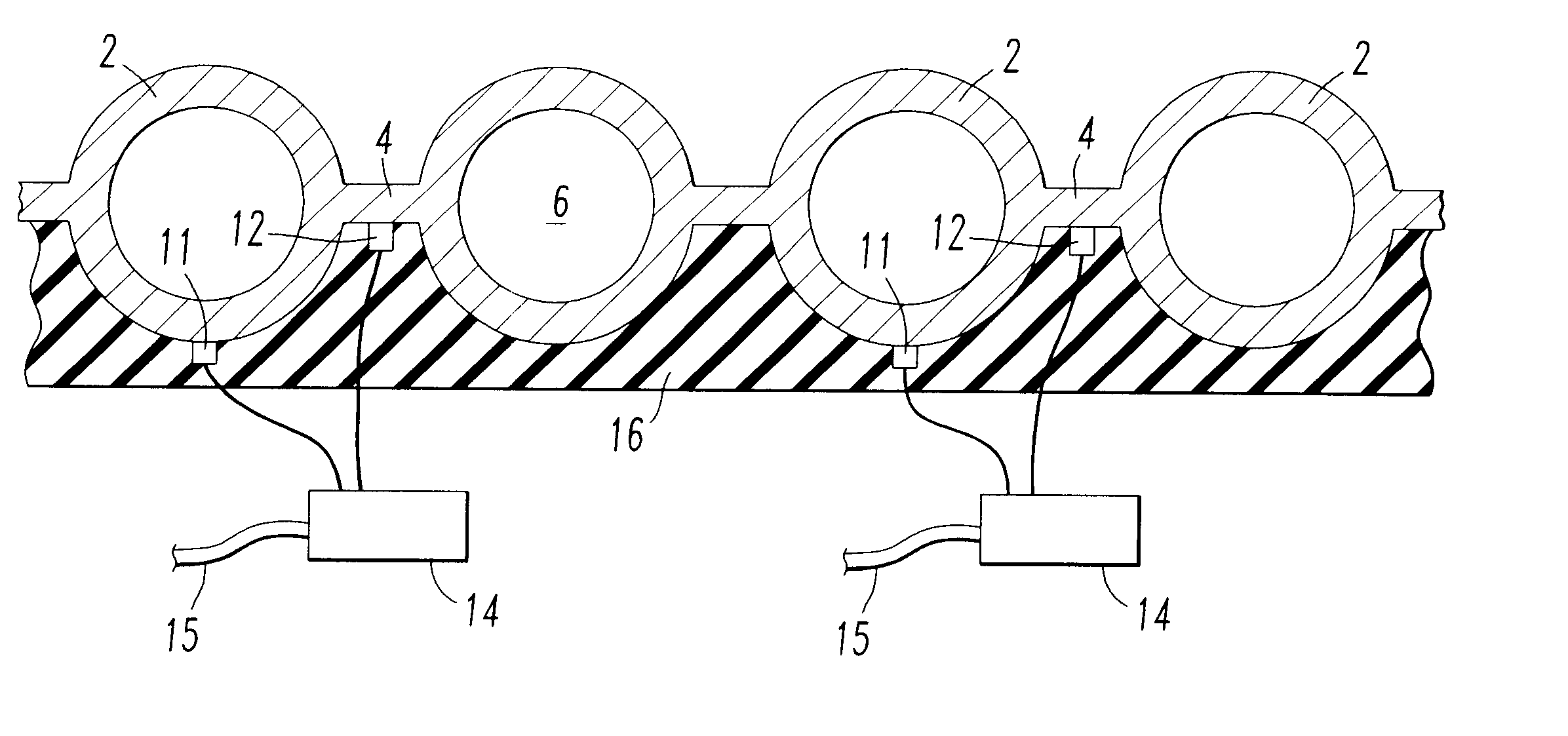
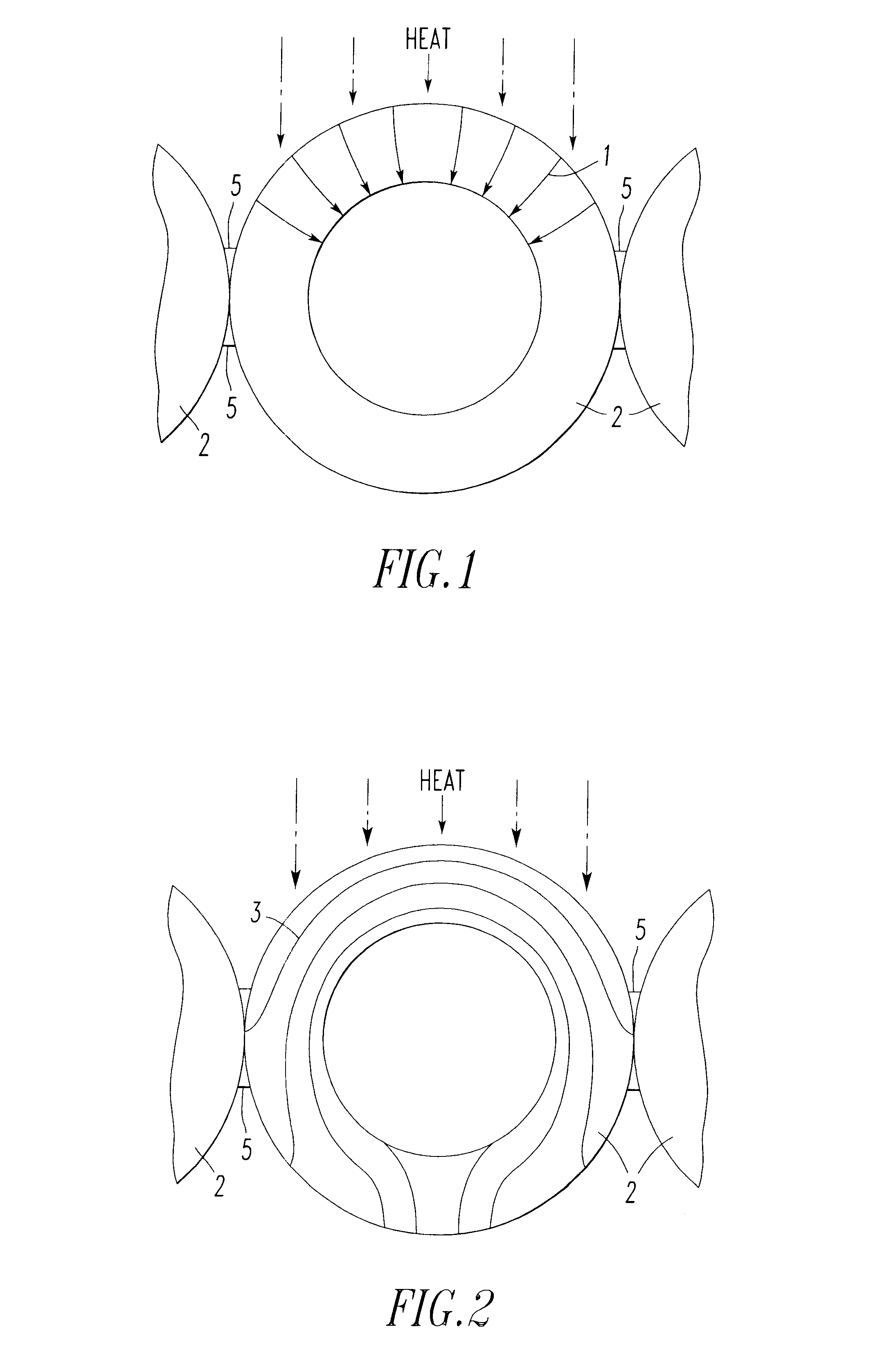
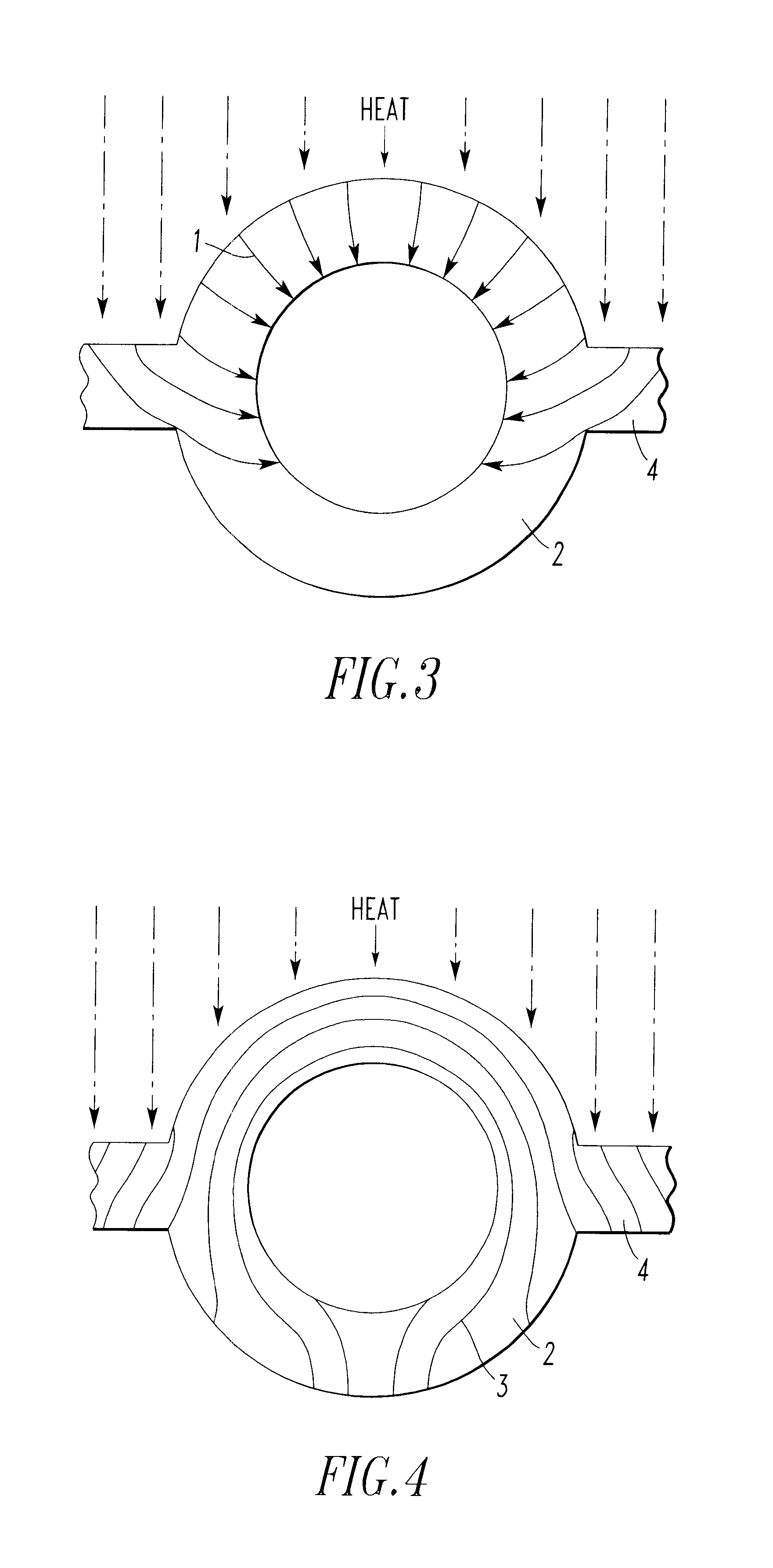
The heat flux received by the waterwall tube webbing may be measured as the temperature difference between the center point temperature of the web and the tube water. With adequate casing insulation, the temperature at a selected point on the fire-side of the web will be approximately the same as the temperature at a corresponding point on the insulated back of the web. Since the water in the tube is acting as a heat sink, the temperature on the back side of a tube will be less than the temperature on the front side of the tube during furnace operation. It is possible to determine and illustrate the heat flux lines and temperature lines that occur in furnace walls. An explanation of this phenomenon is import to an understanding of the present invention.

In the furnace walls of FIGS. 1 and 2 adjacent tubes abut one another and are held together by weld beads 5. In the furnace wall of FIGS. 3 and 4 adjacent tubes are separated and connected together by web 4. Referring to FIGS. 1 throu...


PUM


Abstract

In a method of measuring heat flux and corrosion in a furnace, pairs of thermocouples are attached to the back side of the furnace wall. One thermocouple of each pair is attached to a tube and the second thermocouple is attached to a web connected to that tube. A temperature differential is determined for each pair at selected time intervals. A decrease in the difference between temperature differentials indicates slag on the furnace wall has melted indicating corrosion can be occurring.

Description

FIELD OF INVENTIONThe invention relates to a method for determining the heat flux incident to a furnace wall of the type having water filled tubes connected by webs that are exposed to combustion products; and subsequently, using these heat flux measurements for determining when slag and corrosion occurs on these furnace walls and taking steps to reduce the corrosion rate and / or to reduce the accumulation of the detrimental slag and fouling deposits.BACKGROUND OF THE INVENTIONFor many years electricity has been produced using boilers or furnaces which generate steam that drives a turbine. Many of the furnaces used to produce electricity have walls formed by laterally adjacent water filled tubes welded together. The tubes may abut one another and be welded together along the line of abutment. Alternatively, the tubes often are connected together by webs, one web between each pair of adjacent tubes. These furnace walls are sometimes called water walls. The water in the tubes is heated...

Claims


Application Information

Patent Timeline
IPC IPC(8): F28G15/00G01N17/00G01N25/18F28D7/00
CPCF28D7/0041G01N25/18G01N17/00F28G15/00
Inventor BREEN, BERNARD P.SCHRECENGOST, ROBERT A.
Owner MISSISSIPPI LIME CO
Why Eureka
Try Eureka