Systems for connecting a ground-engaging motive device to a vehicle and related methods

a technology of ground-engaging motive and system, which is applied in the direction of vehicles, vehicle maintenance, endless track vehicles, etc., can solve the problems of not being able to use cranes at locations where space is limited, not being able to meet the needs of over-the-road or highway travel, and being difficult to connect. to achieve the effect of convenient connection

Inactive Publication Date: 2005-02-01
LINK BELT CRANES L P LLLP +1
View PDF22 Cites 24 Cited by
  • Summary
  • Abstract
  • Description
  • Claims
  • Application Information

AI Technical Summary

Benefits of technology

In accordance with a first aspect of the invention, a system intended for use in at least partially connecting a removable ground-engaging motive device (such as a crawler track assembly) to a vehicle (such as a crane) in either an extended or a retracted mounting position using a plurality of connectors is disclosed. The system comprises a first stable mounting structure associated with one of the motive device or the vehicle. The first mounting structure is capable of supporting a first connector in a first position corresponding to the retracted position or supporting the first connector or another connector in a second position corresponding to the extended position. The first mounting structure further includes a first aperture for receiving a second connector in the retracted position and a second aperture for receiving the second connector in the extended position. A first linking structure is associated with the other of the motive device or the vehicle for engaging the first mounting structure in both the extended and retracted positions. The first linking structure includes a first receiver for receiving and guiding the first connector into place such that a third aperture formed in the first linking structure aligns and registers with the first aperture in the retracted position or receiving and guiding either the first connector or another connector mounted in the second position such that the third aperture aligns and registers with the second aperture. The guidance provided by the first receiver in aligning the third aperture with the first or second apertures facilitates connecting the motive device to the vehicle in both the extended and retracted positions.
In one embodiment, the first stable mounting structure is capable of receiving and supporting a first connector and includes a first aperture for receiving a second connector in the retracted position. The first linking structure includes a first receiver that receives and guides the first connector such that a second aperture in the first linking structure is in alignment and registered with the first aperture for receiving the second connector in the retracted position. The extension component includes a third aperture, a fourth aperture, and a second receiver for receiving and guiding the first connector such that the fourth aperture is in alignment and registers with the first aperture in the extended position. The extension component is capable of receiving and supporting a third connector and the first receiver receives and guides the third connector such that the second aperture is in alignment and registered with the third aperture for receiving a fourth connector in the extended position. The guidance provided by the first or second receiver in aligning the first, second, third, and fourth apertures facilitates insertion of the corresponding connectors and hence mounting of the motive device to the vehicle in both the extended and retracted positions.

Problems solved by technology

While crawler tracks are quite useful when the vehicle is moving about the job site in a traveling mode, they are not well-suited for use in over-the-road or highway travel.
While this system has enjoyed considerable success from a commercial standpoint, one factor remains a particular hindrance.
Hence, use of the crane at locations where space is limited, such as between buildings in an urban environment, has been a problem.
Even in cases where space is not a concern, having the crawler tracks always mounted in a fixed position close to the vehicle is deleterious, since this reduces the moment arm and limits the loading capabilities.
Moreover, in view of the specific types of structures required and their special arrangement, it is observed that it is not easily retrofitted onto existing excavators or cranes, as a significant overhaul would be required.
Like the arrangement shown in the '286 patent, this connection system is also not readily adaptable for retrofitting onto existing vehicles without extensive drilling, welding, or other metalworking.

Method used


Image

  • Systems for connecting a ground-engaging motive device to a vehicle and related methods
  • Systems for connecting a ground-engaging motive device to a vehicle and related methods
  • Systems for connecting a ground-engaging motive device to a vehicle and related methods

Examples


Embodiment Construction

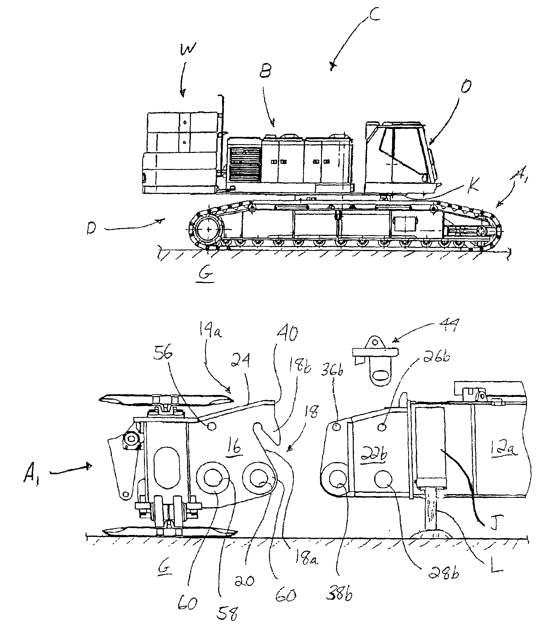
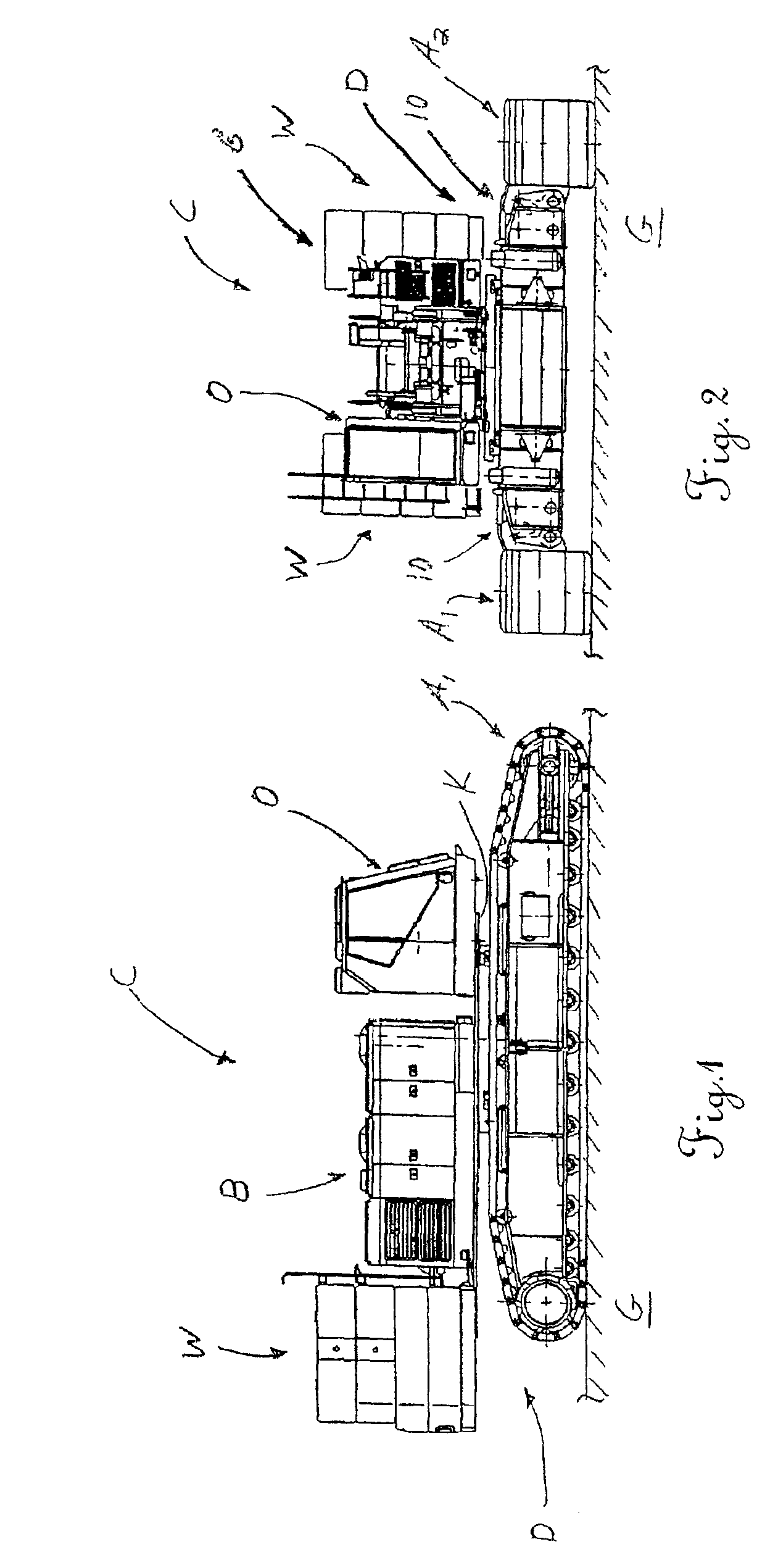
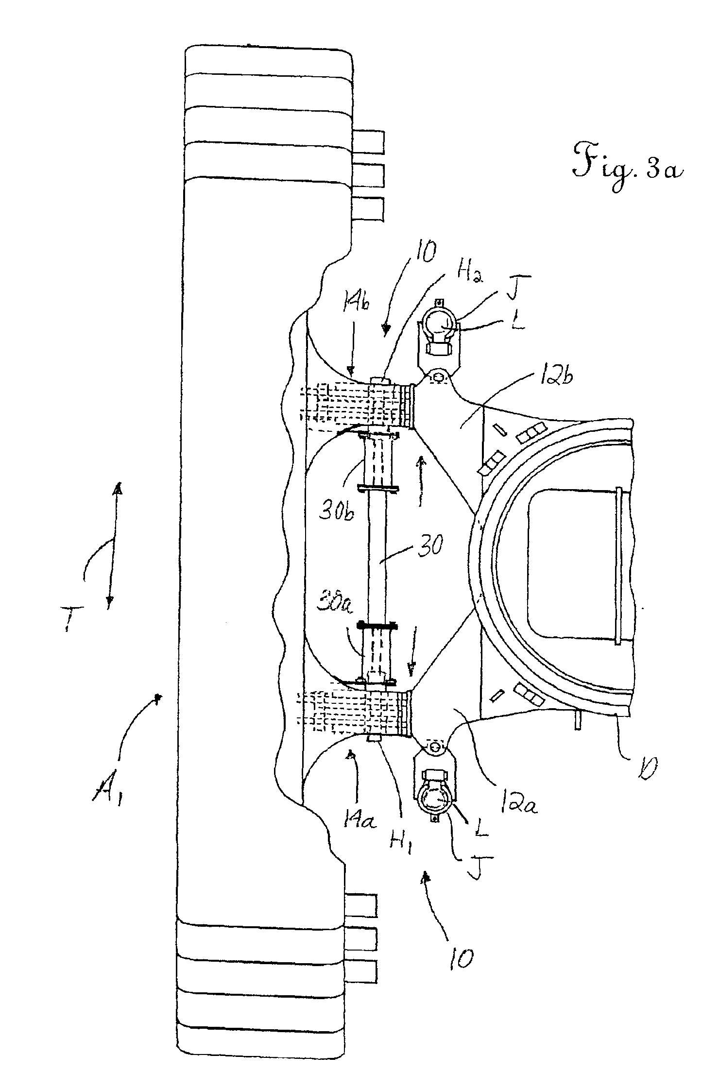
Reference is now made to FIGS. 1 and 2, which show a vehicle in the form of a medium / heavy duty, mobile crawler crane C. As will be recognized, the crane C is generally shown as being assembled and includes a crane base unit (or upper / lower works) B. The base unit B comprises a chassis or carbody D carried on and supported above the ground G by motive devices, such as crawler track assemblies A1, A2 of a type generally known in the art. While the crawler track assemblies A1, A2 are shown on this particular mobile crane C, it is to be understood that the principles of the present invention would also apply to other types of ground-engaging motive devices used on other types of vehicles, including those adapted for direct over-the-road travel as well.

Although not shown in FIG. 1, the crane C typically includes a boom (typically a lattice boom) or other type of live mast, as more fully illustrated in commonly owned U.S. Pat. Nos. 6,131,750 and 5,240,129, the disclosures of which are in...


PUM


Abstract

Disclosed are systems and related methods for mounting a ground-engaging motive device, such as a crawler track assembly, to a vehicle, such as a crane or the like, in either an extended or a retracted position. The systems and methods are adapted to ensure that proper alignment is reliably achieved between the mounting structures on the motive device and the corresponding mounting structures on the vehicle in both the extended and retracted positions. In one embodiment, the system and method are especially adapted for use in extending the crawler track assemblies on certain types of existing cranes without the need for extensive retrofitting.

Description

TECHNICAL FIELDThe present invention relates generally to vehicles having one or more removable ground-engaging motive devices, such as crawler track assemblies and, more particularly, to systems and related methods for easily, efficiently and reliably connecting such a motive device to a vehicle in either an extended or a retracted position.BACKGROUND OF THE INVENTIONHeavy duty, off-the-road vehicles utilize crawler tracks to provide better mobility on uneven ground and for improved traction. In the usual arrangement, the tracks comprise a plurality of links formed together in an endless chain-type fashion with pads formed on the links for engagement with the ground. The multiple pads along the lower run of the endless track in engagement with the ground at any one time provide exceptional traction, while the upper run serves to recirculate the track. Driven sprockets engage the inner surfaces of the links to drive the track along an endless path and thereby provide movement to the...

Claims


Application Information

Patent Timeline
Patent Type & Authority Patents(United States)
IPC IPC(8): B62D55/08B62D55/084
CPCB62D55/084
Inventor MOORE, DONALD E.WILMS, STEVEN F.SUZUKI, YUKITSUGU
Owner LINK BELT CRANES L P LLLP
Why Eureka
Try Eureka