Emergency brake apparatus for vehicle

a technology for emergency brakes and vehicles, applied in the direction of brake systems, brake components, transportation and packaging, etc., can solve the problems of volumetric capacity and weight, hard to employ conventional brakes, and inferior to the case of front and rear tire wheels,

Inactive Publication Date: 2005-02-01
KOMATSU LTD
View PDF6 Cites 9 Cited by
  • Summary
  • Abstract
  • Description
  • Claims
  • Application Information

AI Technical Summary

Benefits of technology

In this case, the present relay valve can be used in a system excellent in a fail safe which can secure a brake operating pressure without applying the pilot oil pressure even when the devices in the ABS are out of order, in comparison with the conventional system which is directly controlled by the electromagnetic solenoid.

Problems solved by technology

In accordance with the structure mentioned above, all of the brake control is achieved by the oil pressure in the construction machine such as the dump truck or the like, however, in this case, the following problems are generated.
This is because in general, the mechanical type brake such as the rear tire wheel brake is not attached to the front tire wheel brake, and the front tire wheel brake can not be used as the emergency brake.
It is advantageous that the emergency brake is divided into the front and rear tire wheels, however, since the conventional brake apparatus can not employ the emergency brake for the front tire wheel, the conventional brake is inferior to the case that the front and rear tire wheels are braked, in view of stopping the vehicle rapidly and stably.
However, in the construction machine, a volumetric capacity and a weight of the apparatus are increased so as to secure a flow rate and a pressure, and there are many restrictions for mounting the apparatus on the vehicle, so that it is hard employ this method.
Further, it is possible to electrically control by using an electromagnetic proportional valve, however, in this case, incidental devices such as controllers, computers, sensors and the like are required, so that the control becomes complex.
There is a risk that any problem is generated in a reliability, in the case that an electrical means is employed as a last means for the emergency stop.
It is possible to use the mechanical type brake together in the same manner as the rear tire wheel, however, a structure in this case becomes complex, the apparatus for the front tire wheel is large sized, and the vehicle becomes expensive.

Method used


Image

  • Emergency brake apparatus for vehicle
  • Emergency brake apparatus for vehicle
  • Emergency brake apparatus for vehicle

Examples


Embodiment Construction

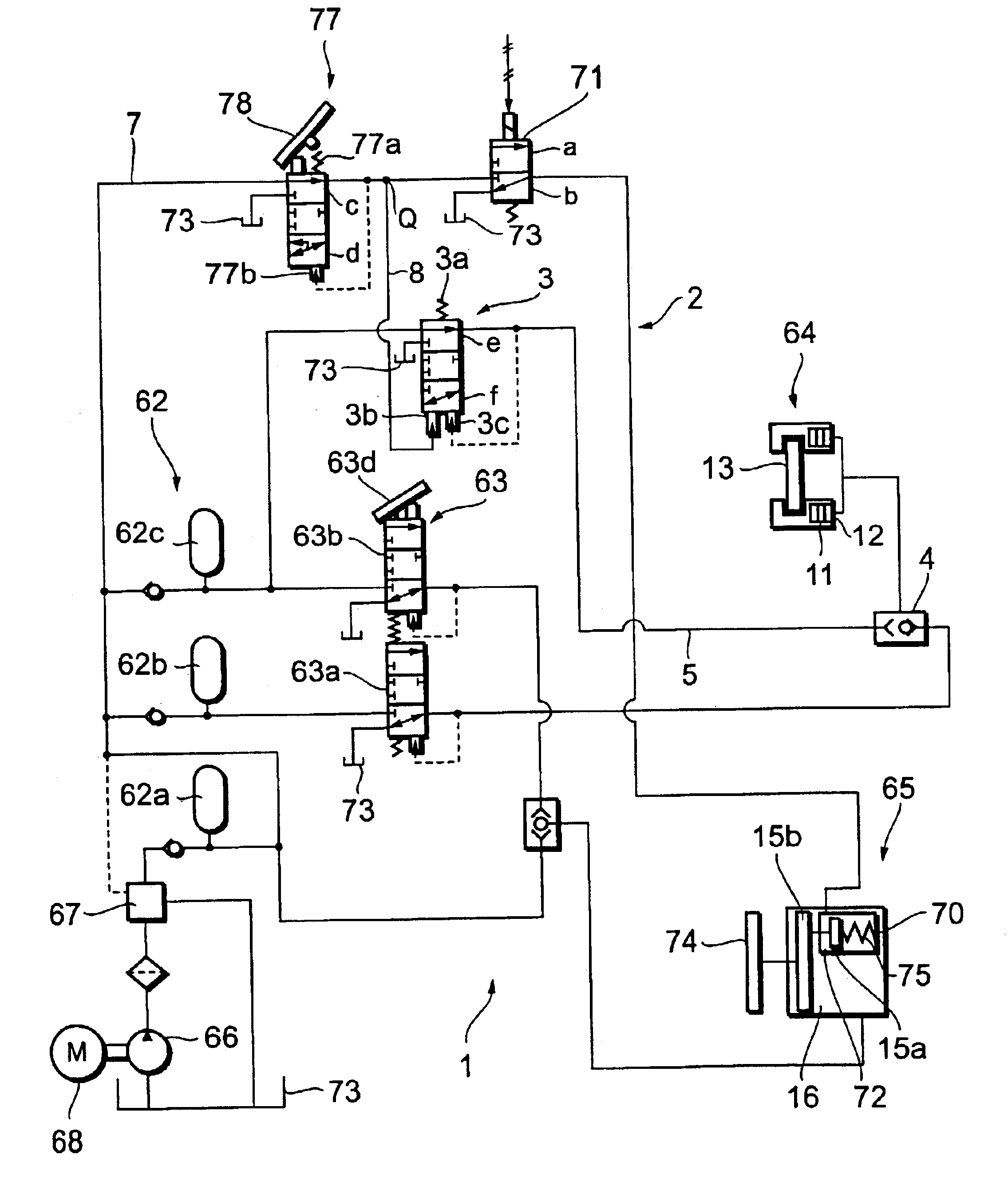
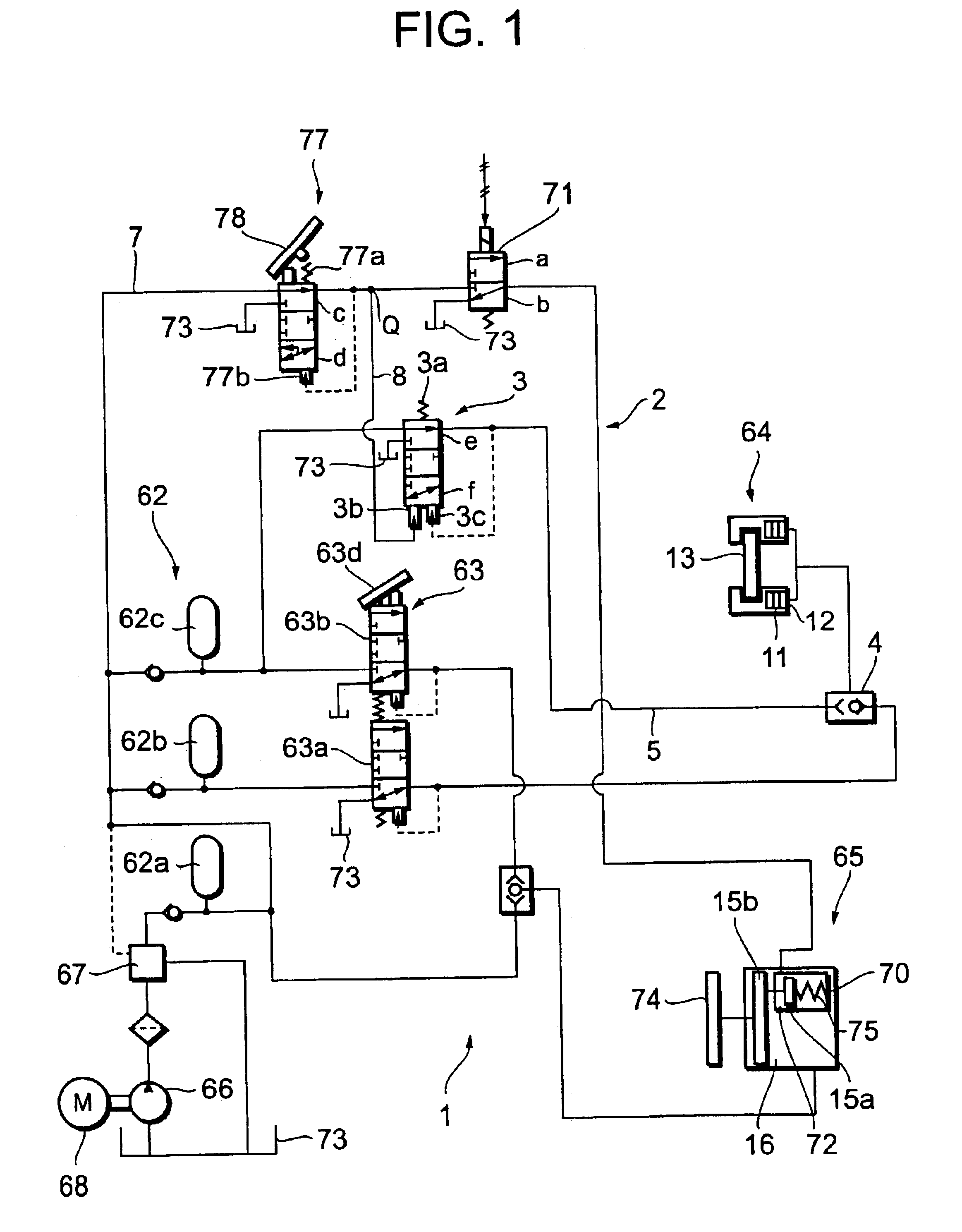
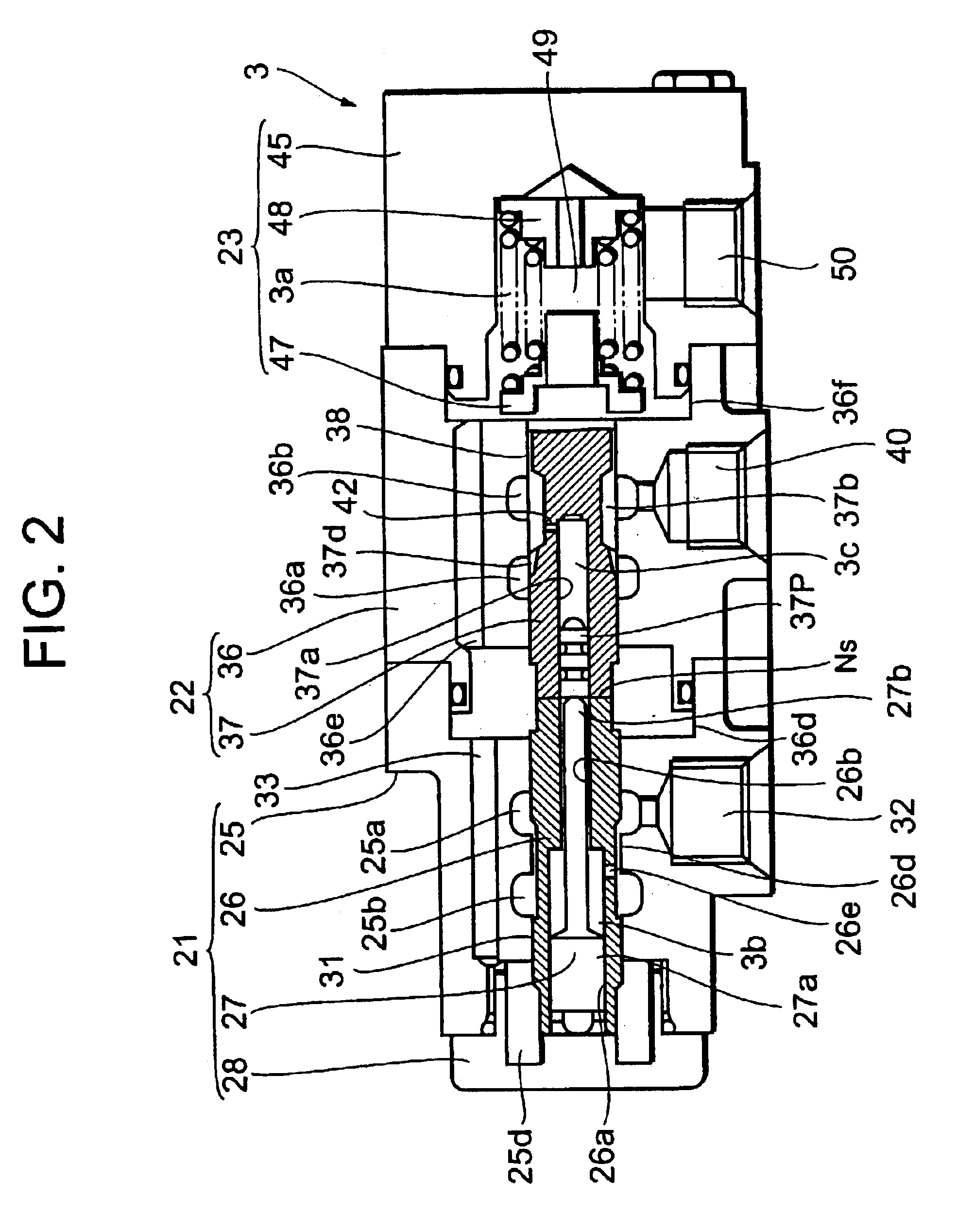
A description will be given of an embodiment of an emergency brake apparatus for a vehicle in accordance with the present invention with reference to FIGS. 1 to 4. In this case, FIG. 1 is a hydraulic circuit diagram of a brake apparatus of a construction vehicle using an emergency brake apparatus 2 in accordance with the present invention, FIG. 2. is an enlarged cross sectional view of a relay valve 3 of the emergency brake 2, and FIG. 3 is a side elevational view of the relay valve 3.

The brake apparatus 1 in FIG. 1 is constructed by adding the emergency brake apparatus 2 for a front tire wheel to a conventional brake apparatus 61 shown in FIG. 5. Accordingly, the same reference numerals are attached to the same parts as those of the device shown in FIG. 5, and a description thereof will be omitted.

The emergency brake apparatus 2 is constructed by adding the relay valve 3 and a shuttle valve 4, and uses a front tire wheel brake 64 as an emergency brake and a braking brake. The relay...


PUM


Abstract

The invention provides an emergency brake apparatus for a vehicle which can brake both of front and rear tire wheels of a vehicle by using an oil pressure, at an emergency time. For this purpose, a pressure oil of a hydraulic power source is changed to a pilot oil pressure which is reduced from a high pressure to a low pressure in correspondence to an operation amount of an emergency brake valve (77) operated at the emergency time, and this pressure is output to a relay valve (3). The pressure oil of the hydraulic power source is increased in an inverse proportional manner from a low pressure to a high pressure in correspondence to the pilot oil pressure, and this pressure is output to a front tire wheel brake (64), thereby urgently braking the front tire wheel.

Description

FIELD OF THE INVENTIONThe present invention relates to an emergency brake apparatus for a vehicle, and more particularly to an emergency brake apparatus used for a dump truck, a construction machine such as a traveling crane or the like, or an industrial vehicle.BACKGROUND OF THE INVENTIONIn conventional, in a brake apparatus of a dump truck traveling on a dirt road, a brake is actuated by pedaling a brake pedal, transmitting an air from a brake valve to a chamber cylinder in both of front tire wheels and rear tire wheels, converting the air into an oil pressure by the chamber cylinder, and operating a wheel cylinder on the basis of the oil pressure.Further, in recent years, in order to improve a reliability and simplify a structure in the brake apparatus, there has been employed a full hydraulic brake system in which both of the front and rear tire wheels are controlled by the oil pressure.In FIG. 5, a brake apparatus 61 employs a plurality of hydraulic accumulators 62a, 62b and 62...

Claims


Application Information

Patent Timeline
Patent Type & Authority Patents(United States)
IPC IPC(8): B60T13/10B60T13/12B66C23/36B60T8/26B66C23/00E02F9/20B60T13/22
CPCB60T8/26E02F9/20B66C23/36B60T13/12
Inventor TANAKA, SATOSHI
Owner KOMATSU LTD
Why Eureka
Try Eureka