Starting clutch and method of controlling the same

a technology of starting clutch and clutch body, which is applied in the direction of mechanical equipment, transportation and packaging, etc., can solve the problems of no torque amplifying function, large sliding amount of torque converter, etc., and achieves small size, light weight, and sufficient rigidity.

Inactive Publication Date: 2005-02-01
NSK LTD +1
View PDF13 Cites 23 Cited by
  • Summary
  • Abstract
  • Description
  • Claims
  • Application Information

AI Technical Summary

Benefits of technology

In some of embodiments, thrust means for fastening the first and the second clutches by thrusting the piston was provided. In this type of the embodiments, the operating mechanism is operated only when the first and second clutches are released and the piston is pushed back in defiance of the thrust of the above described thrust means. Accordingly, since it is enough to allow the operating mechanism to work only when the first and second clutches are released, it is possible to control a power loss of the automobile engine. While, in the embodiments to be hereinafter described, oil pressure is used for the operating mechanism, the power loss of the engine can be controlled similarly by the above described each operating mechanism other than the other.
The piston was integrally formed by a piston for the first clutch and a piston for the second clutch. By the integral forming, it is possible to make the mechanism small in size, light

Problems solved by technology

On the other hand, the torque converter has such a drawback as to have a large amount of sliding at the time of increasing or

Method used


Image

  • Starting clutch and method of controlling the same
  • Starting clutch and method of controlling the same
  • Starting clutch and method of controlling the same

Examples


first embodiment

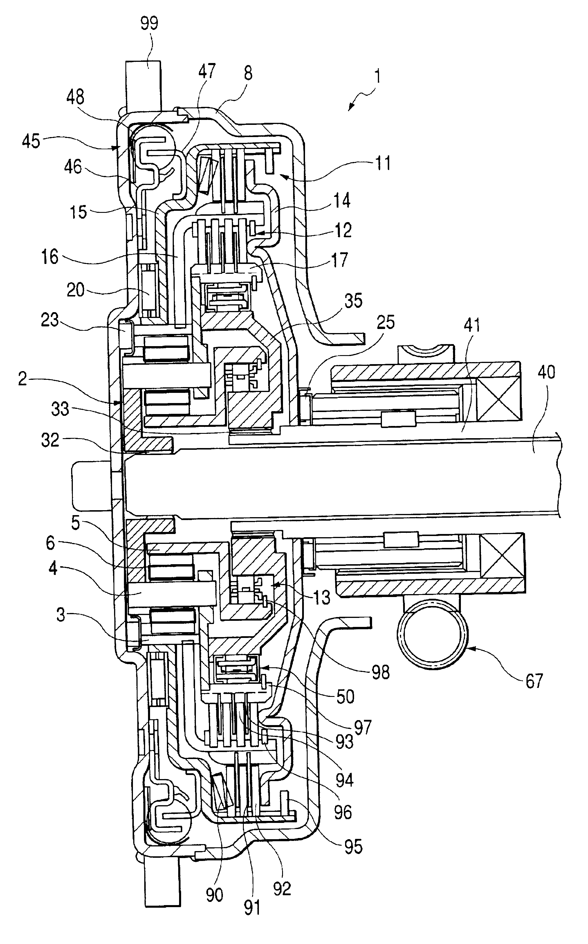
FIG. 1 is an axial sectional view showing a starting clutch of a first embodiment of the present invention. A starting clutch 1 is constituted by a first clutch 11, a second clutch 12, a planetary gear 2 and a damper 45.

The first clutch 11 comprises: a case 8 in which a claw 47 of the damper 45 is fixed and a star gear 99 is provided on an outer periphery side; a clutch case 15 which is supported by the case 8 through a needle bearing 20; a separator plate 92 arranged in the inner periphery of the clutch case 15; a friction plate 91 arranged in the outer periphery of a clutch case 16 of a second clutch 12: and a Belleville spring 90 which is arranged in the inner periphery of the clutch case 15 and biases the separator plate 92 and the friction plate 91 to the piston 14 side.

In an opening end side of the clutch case 15, the separator plate 92, the friction plate 91 and a snap spring 95 for preventing the Belleville spring 90 from slipping off are arranged. The second clutch 12 compr...

second embodiment

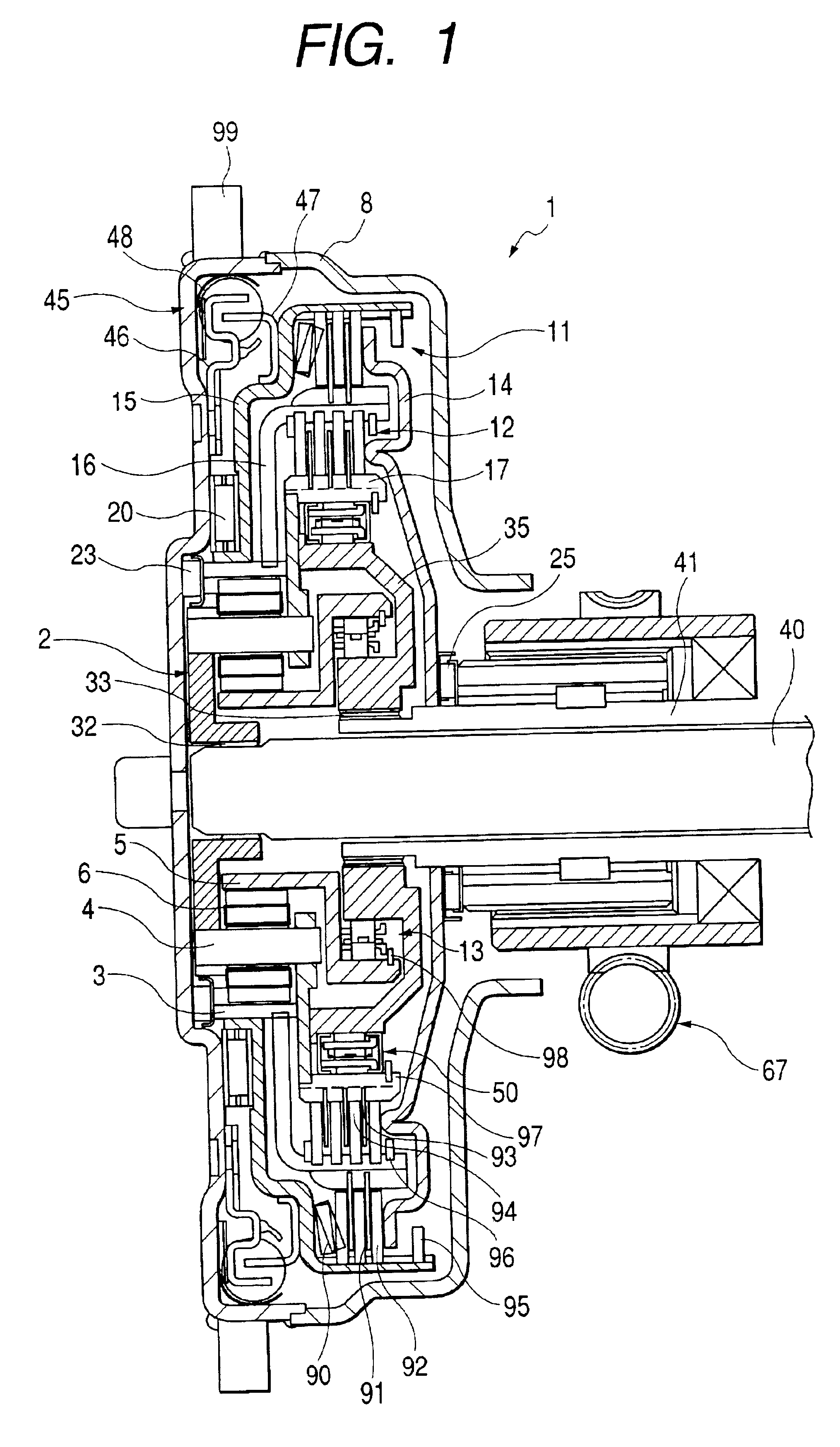
FIG. 2 is an axial sectional view showing a starting clutch of a second embodiment of the present invention. In the second embodiment, the operation of the piston 14 is performed by an electromagnet 69 in place of the ball screw mechanism 67 of the first embodiment. The electromagnet 69 is controlled to ON / OFF by a control circuit not shown. In place of the electromagnet, an electromagnetic type solenoid can be also used. Since the constitution other than the thrust means of the piston 14 is the same as that of the first embodiment, the description thereof will be omitted.

third embodiment

FIG. 3A is an axial sectional view showing a starting clutch of a third embodiment of the present invention. FIG. 3B is a view seen from a direction of an arrow mark A in FIG. 3A. In the third embodiment, the operating mechanism 61, which performs the thrust operation of the piston 14, is constituted by using the release bearing 49 and the ball screw 62. That is, by the operation of the ball screw 62, the release bearing 49 is thrust through a thrust shaft 66 of the ball screw 62, an arm 65, a support 63 and a lever 64. On this occasion, by utilizing the principle of the lever with the support 63 as a fulcrum, more larger thrust load can be obtained. Incidentally, since the constitution of the portion other than the operating mechanism 61 is the same as those of the above described first and second embodiments, the description thereof will be omitted.


PUM


Abstract

A starting clutch includes a planetary mechanism; a first clutch for outputting a torque to an outer diameter portion of the planetary mechanism; a second clutch for outputting the torque to an intermediate portion of the planetary mechanism; and a lock mechanism for locking a reactive force from an inner diameter portion of the planetary mechanism.

Description

BACKGROUND OF THE INVENTION1. Field of the InventionThe present invention relates to a starting clutch usable in place of a torque converter in an automatic transmission (including an automatic control manual transmission or a sequential manual transmission or the like) of an automobile or the like.2. Related Background ArtHitherto, in the automatic transmission, that is AT (automatic transmission), the start of the automobile has been performed by a torque transmission. The torque converter is effective in amplifying the torque and has been mounted on a vast number of AT automobiles because of the smooth torque transmission at the time of increasing or decreasing the torque.On the other hand, the torque converter has such a drawback as to have a large amount of sliding at the time of increasing or decreasing the torque.Thus, in recent years, it has been proposed that the starting clutch can be used in place of the torque converter. Further, by reducing a gear ratio and increasing t...

Claims


Application Information

Patent Timeline
IPC IPC(8): F16H3/54F16H3/44F16D25/0638F16D25/10F16D41/04F16H1/28
CPCF16H3/54
Inventor HAYASHI, YOSHITAKAFUKUSHIMA, HIROSHIOBARA, TAKAOUMEDA, MINAOMINAGI, KEEICHISHOJI, MASAOKINOSHITA, YOSHIOTAKEUCHI, SHIROWATANABE, TADASHINAKAGOMI, HIROFUMIMIYOSHI, TATSURONISHIMURA, SHIGEHARUYABE, HIROSHIHORIUCHI, NOBUHIRO
Owner NSK LTD
Why Eureka
Try Eureka