Apparatus and method for spotting a substrate

a technology of substrate and apparatus, applied in the field of liquid dispensing, can solve the problems of inability to accurately dispense extremely small volumes of liquid, differences in resulting signal intensity or overlap of spots, and inability to approach samples containing relatively fragile macromolecules

Inactive Publication Date: 2005-02-01
APPL BIOSYSTEMS INC
View PDF47 Cites 28 Cited by
  • Summary
  • Abstract
  • Description
  • Claims
  • Application Information

AI Technical Summary

Benefits of technology

A control unit is operatively connected to the positioning means and shifting means for use in successively (i) positioning the tube and associated fiber at a selected deposition position with respect to a substrate, and (i) shifting the fiber to its lowered position, to deposit a selected volume of liquid upon such substrate. In a preferred embodiment, the fiber is (i) laterally flexible and (ii) substantially incompressible along its longitudinal axis. Suitable fibers having such characteristics include, for example, optical fibers. Advantageously, these characteristics permit efficient transfer of motion from the shifting means to the fiber, and the accommodation of variations in the distance between the tube's lower end and the substrate by flexing, or bowing, of the fiber.
In another embodiment, the tube's inner diameter tapers on progressing downwardly to a defined-volume tube end region having the diameter of the orifice. The diameter of the tube end region, in this embodiment, is substantially the same as that of the fiber. The fiber's end, with such in its raised position, is disposed above the tube end region, such that shifting of the fiber from its raised to its lowered position is effective to expel from the tube the volume of liquid contained in the tube end region.
In a preferred embodiment, the fiber is (i) laterally flexible and (ii) substantially incompressible along its longitudinal axis. For example, the fiber can be an optical fiber. Advantageously, these characteristics permit efficient transfer of motion from the shifting means to the fiber, and the accommodation of variations in the distance between the tube's lower end and the substrate by flexing, or bowing, of the fiber.
In another embodiment, the apparatus is adapted for use in micro-spotting a predetermined volume of one or more selected liquids simultaneously at multiple selected deposition regions on a substrate. In this embodiment, the apparatus further includes a plurality of tubes, and associated fibers and shifting means. In an exemplary arrangement, the tube end regions have diameters of less than about 200 μm, the fibers are flexible fibers, and the fibers in their lowered positions are adapted to make contact with the substrate. Additionally, fiber flexing accommodates variations in the distance between the tubes' lower ends and the associated positions on the substrate.
In one embodiment, the array-producing apparatus includes a manifold, or channel assembly, having a plurality of capillary channels, each adapted to hold a selected liquid. The channels have opposite upper-end and lower-end openings, and inner diameters that decrease on progressing from the upper- to the lower-end openings. The lower-end openings, in this embodiment, define the pattern and center-to-center spacing, or pitch, of the spot array. A support is movable between raised and lowered positions with respect to the manifold. A plurality of fibers are suspended from the support for movement therewith. Each fiber is adapted to move longitudinally within an associated channel, as the support is moved between its raised and lowered positions. Movement of the fibers from their raised to lowered positions is effective to deposit a selected volume of liquid from each channel in the manifold.

Problems solved by technology

This is especially true in situations involving expensive compounds.
For example, micropipettes are generally incapable of accurately dispensing the extremely small volumes of liquid called for by many present-day protocols.
With regard to pens and quills, a number of problems need to be resolved relating to the differences in size and shape of the spots which are placed (which can lead to differences in resulting signal intensity or overlap of spots), “missed spots” (where little or no sample is placed on the surface), and the overhead associated with cleaning and reloading.
This approach is not acceptable for the spotting of samples containing relatively fragile macromolecules, as they can become sheered or otherwise damaged.
Further, ink-jetting devices are associated with a high degree of splattering, thereby presenting a substantial risk of contamination, particularly for closely spaced spots.
As an additional disadvantage, most of the known spotting devices require very precise placement of the spotting head relative to the substrate surface.
Variations in the distance between the spotting head and the substrate surface can result in inconsistent spot sizes and / or missed spots.

Method used


Image

  • Apparatus and method for spotting a substrate
  • Apparatus and method for spotting a substrate
  • Apparatus and method for spotting a substrate

Examples


Embodiment Construction

The following discussion of the preferred embodiments of the present invention is merely exemplary in nature. Accordingly, this discussion is in no way intended to limit the scope of the invention.

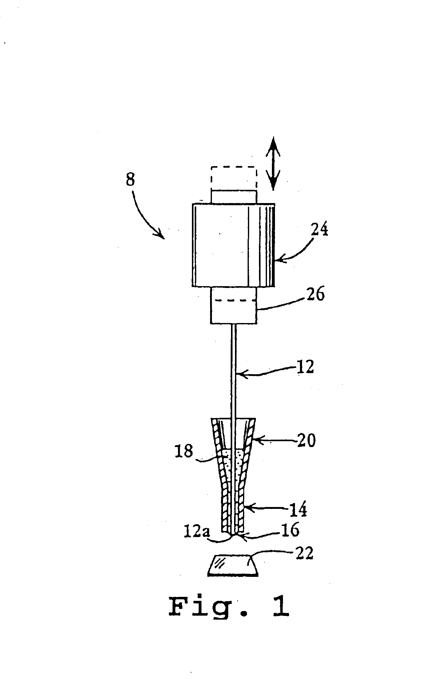
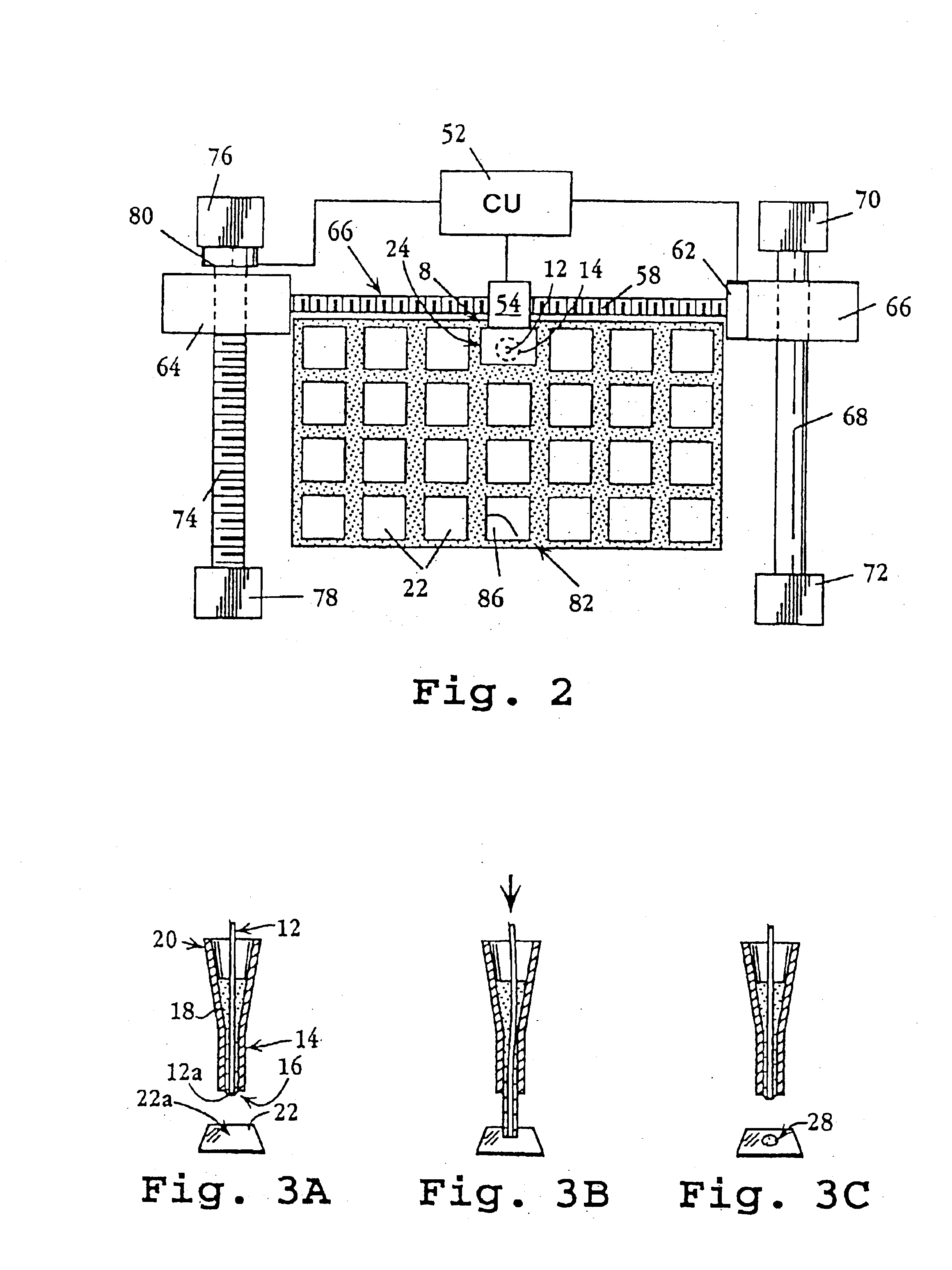
One aspect of the invention provides a device for dispensing a small volume of a liquid reagent on a substrate. Generally, the device includes a tube adapted to contain the liquid. An elongate fiber is disposed within the tube for axial movement therein between raised and lowered positions. Upon shifting or oscillating the fiber between its raised and lowered positions, a liquid spot can be formed at a selected position on the substrate.

In one exemplary arrangement of a spotting device, denoted generally as 8 in FIG. 1, a fiber, indicated as 12, extends longitudinally within a tube, denoted as 14, having an orifice 16 at its lower end. Tube 14 is adapted to contain a liquid reagent, such as 18, for controlled deposition on a substrate, as discussed more fully below. Tube 14 can be formed, ...


PUM

PropertyMeasurementUnit
diameteraaaaaaaaaa
diameteraaaaaaaaaa
diameteraaaaaaaaaa

Abstract

The present invention provides a method and apparatus for dispensing a small volume of a selected liquid, such as a biological sample or reagent, onto a substrate. The device includes a tube adapted to contain the liquid. An elongate fiber is disposed within the tube for axial movement therein between raised and lowered positions. Upon shifting or oscillating the fiber between its raised and lowered positions, a liquid spot can be formed at a selected position on the substrate. The device is readily adaptable for the production of micro-arrays having a great number of individual spots.

Description

FIELD OF THE INVENTIONThe present invention relates to the dispensing of liquids. More particularly, the invention provides an apparatus and method of use for spotting liquids, such as biological samples or reagents, onto a substrate.BACKGROUND OF THE INVENTIONTarget compounds, or analytes, present within a sample can often be identified through the controlled exposure of the sample to an appropriate probe, with subsequent detection of a resulting reaction. In a typical arrangement, a sample of a test solution containing an analyte of interest is exposed to a probe carrying a detectable reporter. The probe is chosen such that it can specifically bind the analyte, e.g., by hybridization of complementary nucleotide sequences, or antibody-antigen interactions. After excess probe material has been removed, e.g., washed away, specific binding of the probe to the analyte can be detected.As the sensitivity of analytical techniques continues to improve, it is increasingly desirable to carry...

Claims


Application Information

Patent Timeline
Patent Type & Authority Patents(United States)
IPC IPC(8): B01L3/02B01J19/00G01N35/10G01N35/00G01N37/00C40B60/14
CPCB01J19/0046B01L3/0244B01L3/0251B01L3/0262G01N35/1016G01N35/1067Y10T436/25B01J2219/00376B01J2219/00387B01J2219/00527B01J2219/00585B01J2219/00596B01J2219/00605B01J2219/0061B01J2219/00612B01J2219/00626B01J2219/0063B01J2219/00637B01J2219/00659B01J2219/00689B01L2300/0819B01L2300/0838B01L2400/028B01L2400/0406C40B60/14G01N35/1074G01N2035/00237G01N2035/1034G01N2035/1037G01N2035/1039G01N2035/1069Y10T436/2575B01J2219/00369
Inventor VANN, CHARLES S.BRYNING, ZBIGNIEW
Owner APPL BIOSYSTEMS INC
Why Eureka
Try Eureka