Microwave tuners for wideband high reflection applications

a wideband, high-reflective technology, applied in the direction of measuring devices, instruments, electrical measurements, etc., to achieve the effect of high reflection capability

Inactive Publication Date: 2005-02-01
TSIRONIS CHRISTOS
View PDF6 Cites 18 Cited by
  • Summary
  • Abstract
  • Description
  • Claims
  • Application Information

AI Technical Summary

Benefits of technology

In order to avoid the shortcomings of the traditional pre-matching tuner approach we propose a new tuner structure, which uses two RF slugs, which can be adjusted to certain horizontal distance among themselves and constant relative vertical position, but move simultaneously after that, both horizontally and vertically. This new technique utilizes, in fact, a static kind of pre-matching mechanism, since the reflection vectors of both RF slugs are adding, but, since both slugs move simultaneously horizontally and vertically, the relative phase between the two reflection vectors does not change and by consequence the total reflection vector does not

Problems solved by technology

The problem of high reflection factor tuning, required for Load Pull and Noise testing of high power and low noise transistors, using automatic or manual microwave tuners has been addressed up to date in different manners as follows:
1. Using (pre-matching) transforming networks (70,71) on the test fixtures (62) (FIG. 1) or “on-chip”. This allows a static pre-matching, in which the characteristic impedance of the test system is transformed to be close to the conjugate complex of the internal impedance of the DUT (device under test, 63), thus making further tuning by the external controllable automatic or manual tuners of the test setup, connected to the ports (66,67) of the test fixture (62), easier and more accurate. This technique has been used for long time in RF technology, but has the disadvantage of not being able to cover a significant frequency bandwidth simultaneously or match a variety of DUT's (63) using the same transforming networks (70,71), which said networks must be re-designed and manufactured for other frequencies and DUT's with different internal impedance.
2. Using Pre-matching tuners (FIG. These devices have the capability of generating very high reflection factors using two or more RF slugs (6,7) in series and positioning them in such a manne

Method used


Image

  • Microwave tuners for wideband high reflection applications
  • Microwave tuners for wideband high reflection applications
  • Microwave tuners for wideband high reflection applications

Examples


Embodiment Construction

This invention is described in the following with reference to the FIGS in which like numbers represent the same or similar elements:

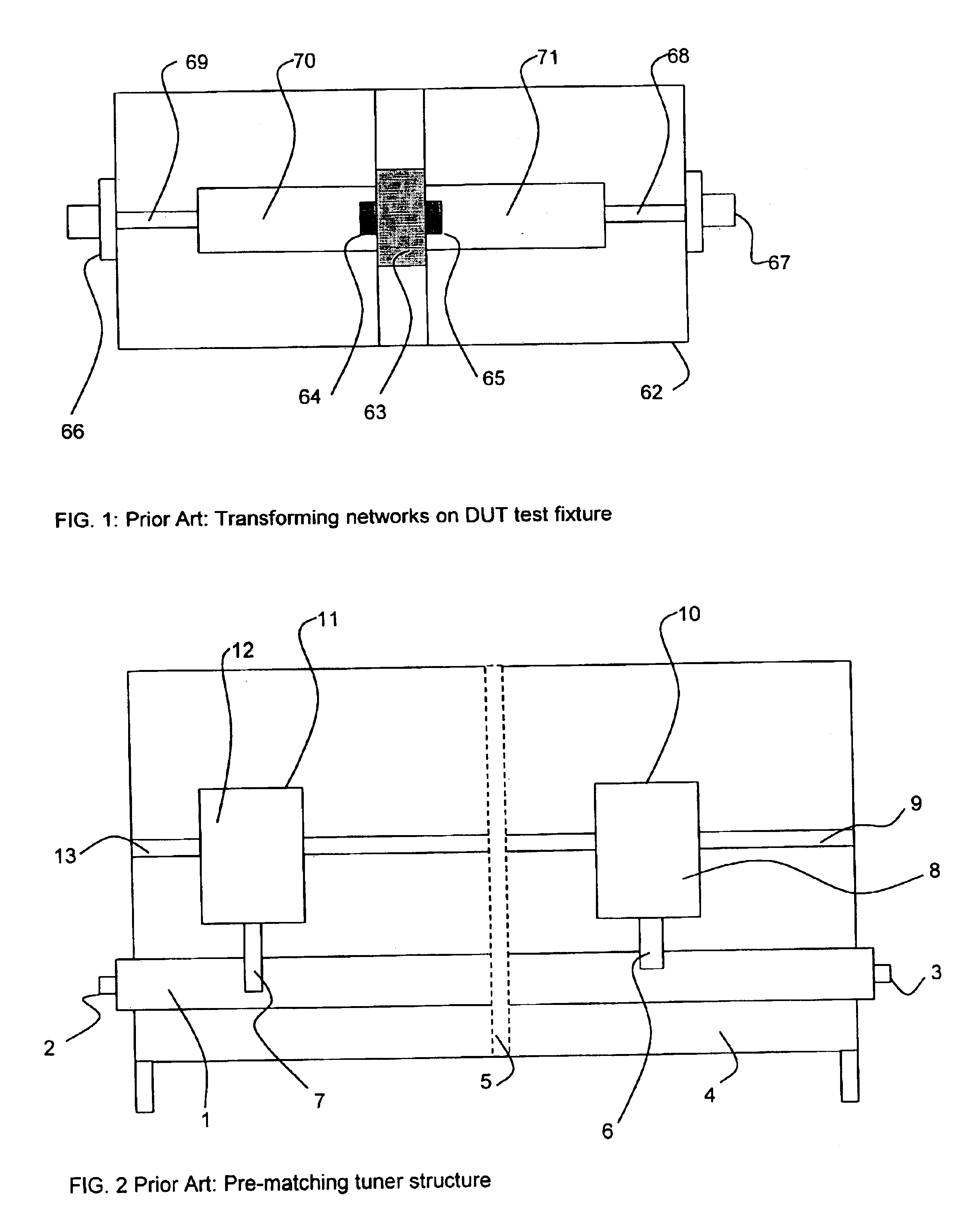
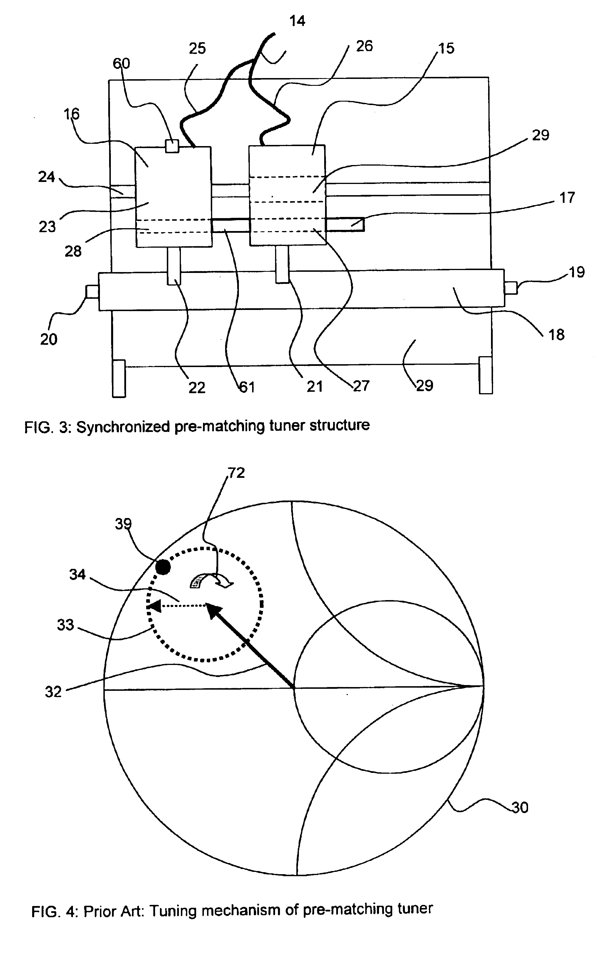
We propose controllable microwave tuners, which include two or more RF slugs, connected in series in the same airline (or slabline for practical applications), (FIG. 3). The main difference to existing pre-matching tuners (FIG. 2) consists in the different way of controlling the position and the RF operation of the RF slugs (21,22), included in the new tuners (29). Instead of moving the two (or more) RF slugs (6, 7) in tuner (4) independently, the pre-matching slug (7) being positioned before the actual tuning with slug (6) starts, the new tuners (29) control both RF slugs (21,22) both horizontally and vertically simultaneously. This has a major effect on the RF behavior of the new tuners (29): Instead of covering only a small section of the Smith Chart at high reflection, (dotted circle (33) in FIG. 4, FIG. 7), the new tuners cover the entire Smith Ch...


PUM


Abstract

High reflection load pull tuners are proposed, which include two or more RF probes, placed in series into the same slotted airline (slabline) and being controlled simultaneously horizontally and vertically by remote electric control, allowing the creation of controlled reflection factors which are distributed over and cover the entire Smith Chart, from very low reflection factors up to very high reflection factors and a method allowing to align such tuners and to calibrate such tuners on a vector network analyzer.

Description

CROSS-REFERENCE TO RELATED APPLICATIONSNot Applicable.STATEMENT REGARDING FEDERALLY SPONSORED RESEARCH OR DEVELOPMENTNot ApplicableREFERENCE TO A SEQUENCE LISTING, A TABLE, OR A COMPUTER PROGRAM LISTING COMPACT DISC APPENDIXNot ApplicableBACKGROUND OF THE INVENTION1. Field of the InventionThis invention describes a new solution for obtaining user controlled high reflection factors using wideband load pull microwave tuners.2. Description of the Prior ArtMicrowave testing of low noise and high power semiconductor devices, such as transistors, require impedance generation microwave tuners. These tuners create a controlled reflection factor which is presented to the device under test (DUT) by means of test fixtures and other microwave transmission media. Modern microwave transistors, especially low noise and high power devices have very low or very high internal impedances at their input or output ports. In order to match those impedances using microwave impedance transformers, commonly...

Claims


Application Information

Patent Timeline
IPC IPC(8): G01R27/00G01R27/32
CPCG01R27/32
Inventor TSIRONIS, CHRISTOS
Owner TSIRONIS CHRISTOS
Why Eureka
Try Eureka