Sound field correction circuit

a correction circuit and sound field technology, applied in the field of sound field correction circuits, can solve the problems of increasing the size affecting the quality of the sound image, and the inability to reproduce from such a point of view, and achieve the effect of low cos

Inactive Publication Date: 2005-02-01
SONY CORP
View PDF14 Cites 20 Cited by
  • Summary
  • Abstract
  • Description
  • Claims
  • Application Information

AI Technical Summary

Benefits of technology

It is an object of the present invention to provide a sound field correction circuit for a surround playback apparatus wherein a decoding circuit is constructed...

Problems solved by technology

Particularly, when sound reflected from the side becomes large in comparison to the direct sound, then the extensiveness of the sound image increases.
The problem is how to produce the sound so that either purpose, as described above, can be achieved.
Reproduction from such a point of view, as described above, is basically impossible with stereo signals recorded by an ordinary method.
Because the decoding circuit performs such co...

Method used


Image

  • Sound field correction circuit
  • Sound field correction circuit
  • Sound field correction circuit

Examples


Embodiment Construction

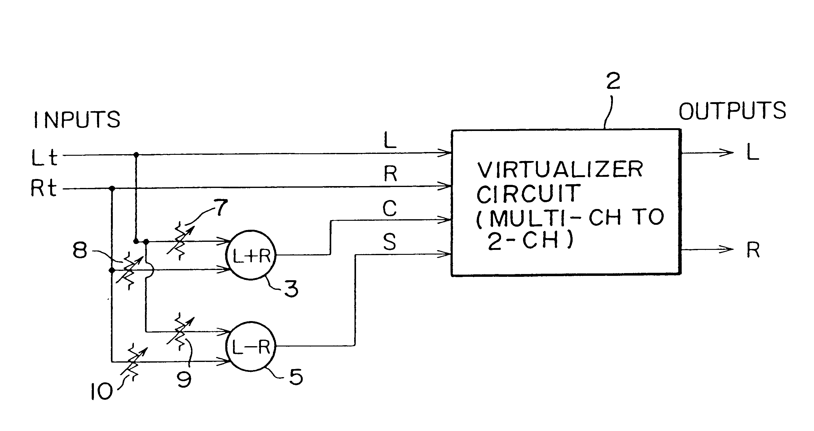
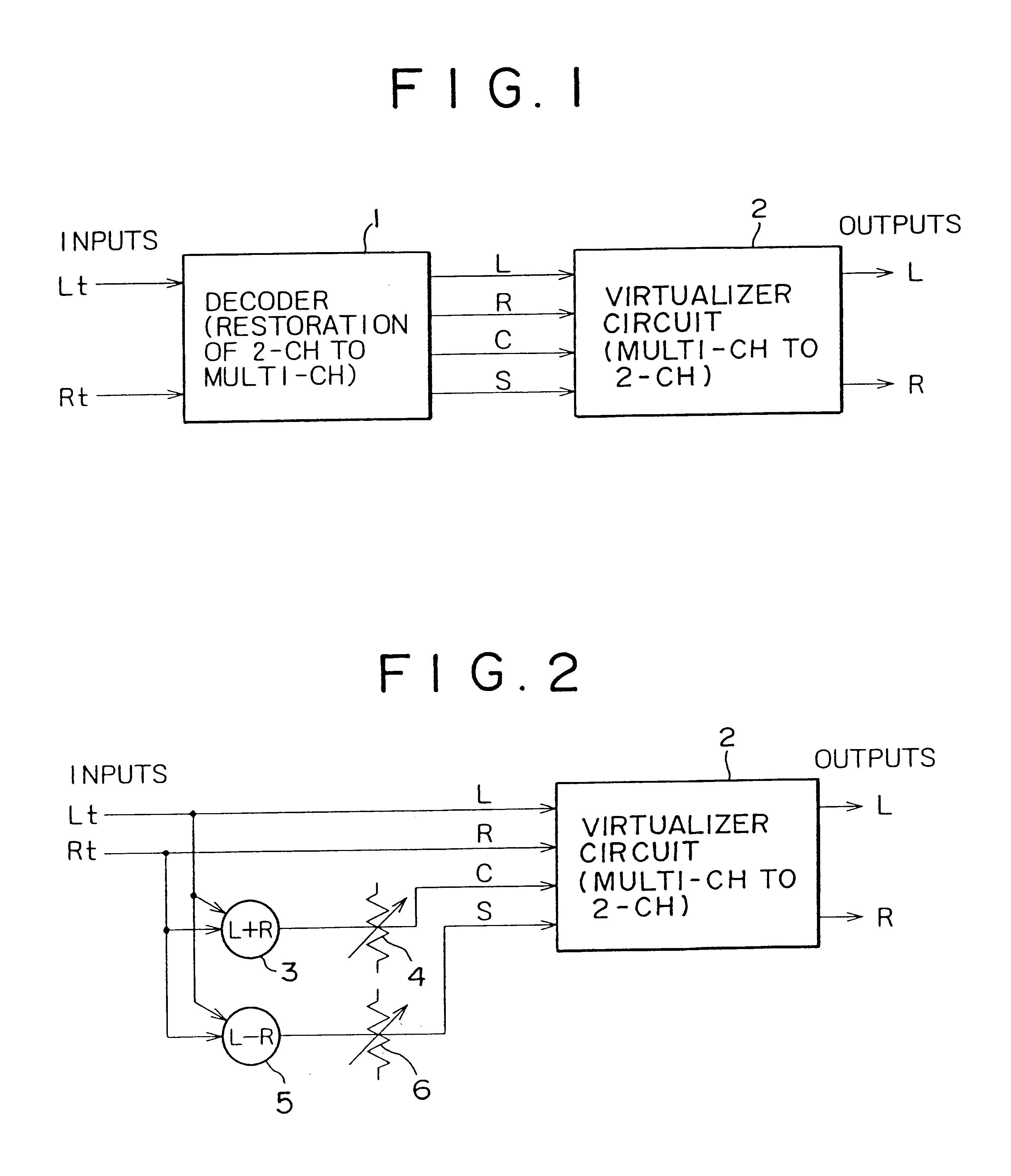
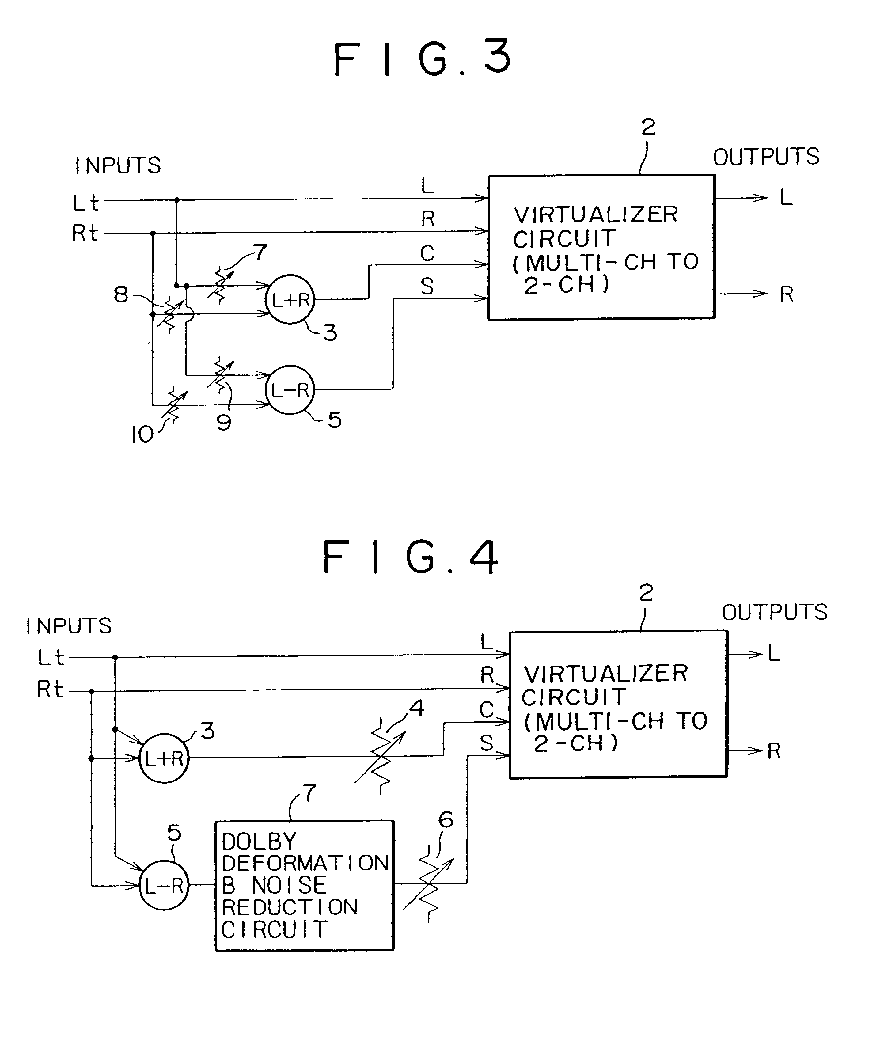
Referring first to FIG. 2, a circuit block diagram is shown of a sound field correction circuit to which the present invention is applied. The sound field correction circuit includes a virtualizer circuit 2, an adder 3, a subtractor 5, and a pair of level adjusting volumes 4 and 6.

In the sound field correction circuit, input stereo signals Lt, Rt are first sent as L (left channel) and R (right channel) signals directly to the virtualizer circuit 2.

The input stereo signals Lt, Rt are also sent to the adder 3 and the subtractor 5. Then, the adder 3 adds the stereo signals Lt and Rt (=Lt+Rt) to produce a C (center channel) signal while the subtractor 5 calculates the difference between the stereo signals Lt and Rt (that is, Lt−Rt) to produce an S (surround channel) signal. The adder 3 and the subtractor 5 can each be readily formed from an amplification circuit which may employ, for example, an operational amplifier.

The L (left channel), R (right channel), C (center channel) and S (sur...


PUM


Abstract

The invention provides a sound field correction circuit for a surround playback apparatus wherein a decoding circuit is formed from a comparatively simple circuit and similar effects to those of a ordinary sound field correction circuit can be achieved at a reduced cost. A sound field correction circuit includes a decoding circuit for restoring 2-channel stereo signals encoded for a multi-channel surround effect to obtain multi-channel surround signals. The decoding circuit includes an adder for adding the encoded 2-channel stereo signals to each other, a subtractor for subtracting one of the encoded 2-chhanel stereo signals from the other, a level adjusting volume for adjusting the output level of the adder, and another level adjusting volume for adjusting the output level of the subtractor. An output of the level adjusting volume is used as a center channel signal while an output of the level adjusting volume 6 is used as a surround channel signal.

Description

BACKGROUND OF THE INVENTION1. Field of the InventionThis invention relates to a sound field correction circuit for a surround acoustic system, and more particularly to simplification of a decoding circuit for obtaining multi-channel surround signals from 2-channel stereo signals encoded for a multi-channel surround effect.2. Description of the Related ArtIt is known that a human being orients low-pitched sound sources based on a time difference and / or phase difference between sounds arriving at each ear, but orients high-pitched sound sources based on the strength difference between incoming sounds to each ear.Also, it is known that a person's sense of hearing blends sounds from a plurality of sound sources to form a single sound image. In this instance, the sounds are more likely to be blended when the signals are coherent and the arrival times of the signals are limited to a certain range. The orientation of a composite sound image, when two coherent sound sources are involved, de...

Claims


Application Information

Patent Timeline
IPC IPC(8): H04S1/00H04S5/02
CPCH04S1/002H04S2400/01H04S3/02G10L19/008
Inventor MAEJIMA, YOSHIMICHI
Owner SONY CORP
Why Eureka
Try Eureka