Method for computing and using future costing data in signal routing

a signal routing and future costing technology, applied in the field of programmatic logic devices, can solve the problems of remaining future cost of existing systems, and achieve the effect of reducing the run-time needed and improving the run-tim

Inactive Publication Date: 2005-02-01
XILINX INC
View PDF6 Cites 75 Cited by
  • Summary
  • Abstract
  • Description
  • Claims
  • Application Information

AI Technical Summary

Benefits of technology

“Future costing” is a well-known method used to improve the run-time required to route signals in integrated circuits. The present invention involves a new method for determining and using future cost in routing. To the router, the integrated circuit interconnect is modeled using a routing graph, containing a set of nodes and directed edges. The nodes in the graph represent conductors in the integrated circuit. Edges are present between nodes that correspond to conductors that can be electrically connected to one another. In one embodiment of the present invention, a two-dimensional table is used to store future cost data. The entries in the table are indexed by x and y distances between nodes in the routing graph. To populate the table with future cost values, pre-routing is performed from a specially chosen source node to other nodes in the routing graph. At each node visited during pre-routing, both the cumulative routing cost and the x and y distances from the source node are computed. If there is no entry in the table that corresponds to the specific x, y-distance, the cumulative routing cost is entered into the corresponding position in the table. If the table contains existing future cost data corresponding to this distance, the table entry is set equal to the cumulative routing cost if the cumulative routing cost is less than the value of the existing future cost data. Otherwise, the existing future cost remains. The normal routing of a user's signals commences after the pre-routing is completed. During routing, values from the future cost table are used to reduce the run-time needed for routing a design's signals.

Problems solved by technology

Otherwise, the existing future cost remains.

Method used


Image

  • Method for computing and using future costing data in signal routing
  • Method for computing and using future costing data in signal routing
  • Method for computing and using future costing data in signal routing

Examples


Embodiment Construction

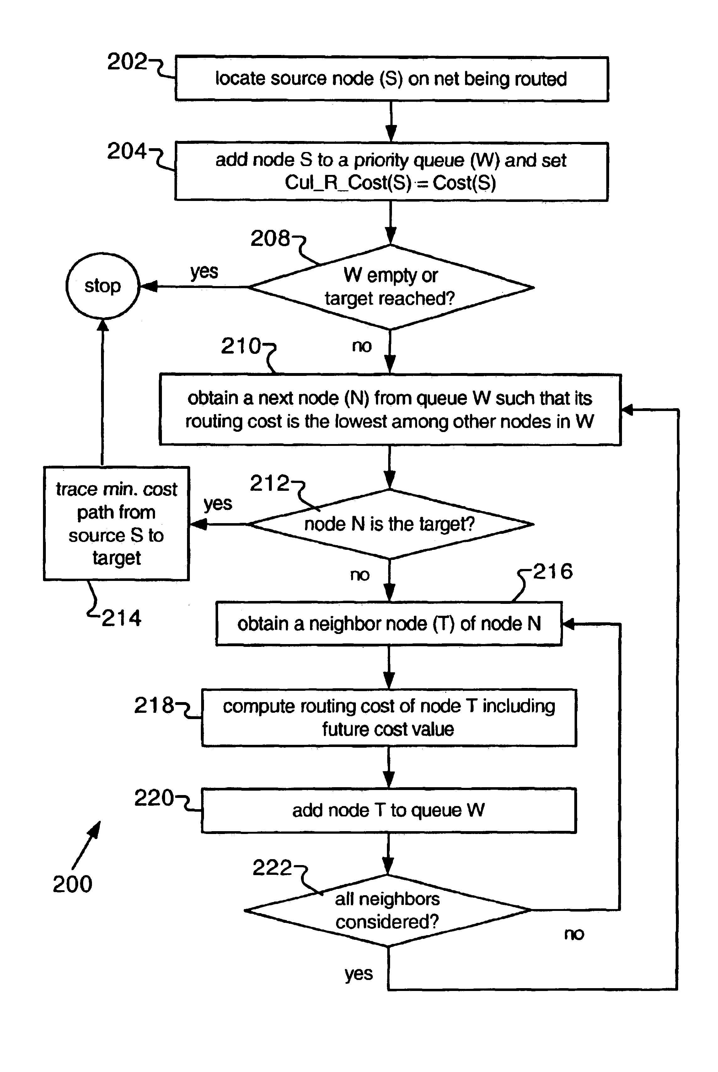
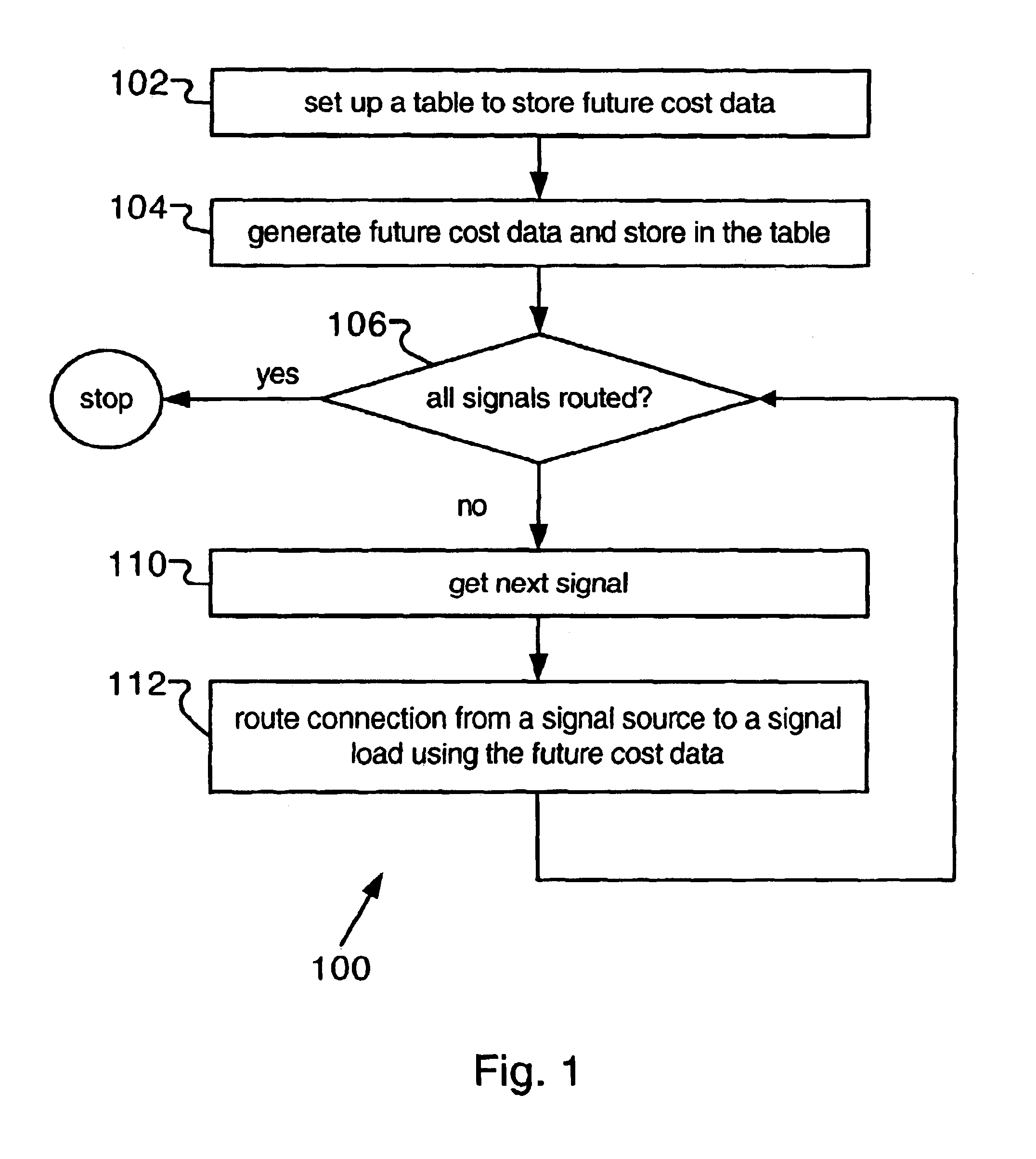
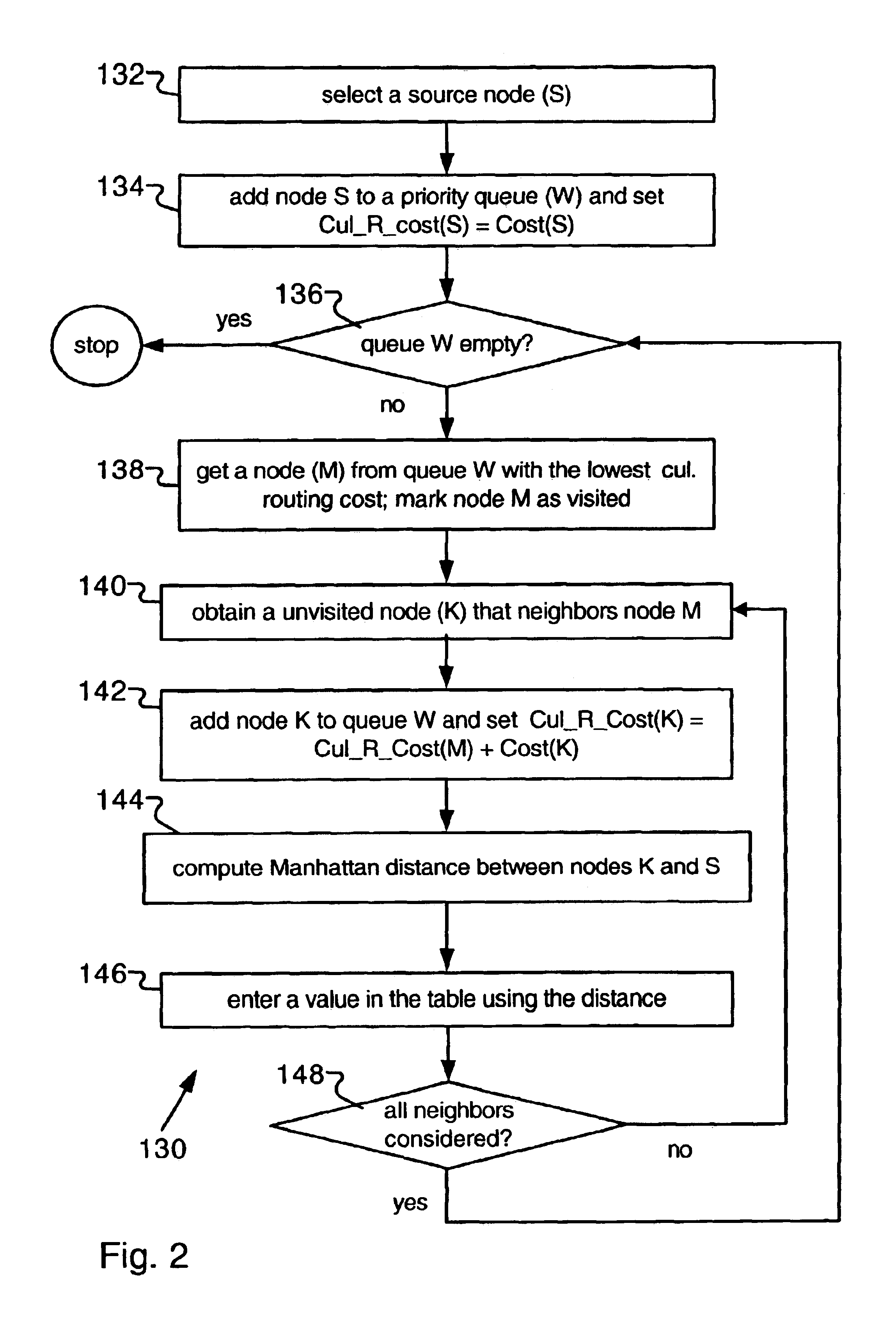
The present invention relates to a new method for routing signals, In the following description, numerous specific details are set forth in order to provide a more thorough understanding of the present invention. However, it will be apparent to one skilled in the art that the present invention may be practiced without these specific details. In other instances, well-known features have not been described in detail in order to avoid obscuring the present invention.

A widely used algorithm used for routing signals in PLD devices is a variant form of the well-known maze router, as described in C. Y. Lee, “An Algorithm for Path Connections and its Applications,” in IRE Trans. on Electronic Computers, Vol. EC=10, 1961, pp. 346-365. This technique is general and adapts very well to some PLD interconnect architectures, such as the FPGA routing fabric. From the router's perspective, the integrated circuit interconnect as modeled by a “routing graph”, containing a set of nodes and directed ed...


PUM


Abstract

A systematic method for calculating future cost is disclosed. Pre-routing is performed from a source node to other nodes through a series of neighboring nodes. At each node in the pre-routing, the cumulative routing cost and Manhattan distance are calculated. This cumulative routing cost is used as a new future cost for a specific distance if it is lower than or there is no existing future cost for that distance. A table can be used to store the future cost data. During routing, the recorded future cost is added to the cumulative cost of a node to help guide the routing, improving router run-time.

Description

FIELD OF THE INVENTIONThe present invention relates to programmable logic devices (PLDs), and more particularly to a method for routing signals in programmable logic devices.BACKGROUND OF THE INVENTIONA programmable logic device (PLD) is a digital circuit implementation platform that can be configured by the end user to implement a logic circuit of their choice. The two most common types of PLDs are field-programmable gate arrays (FPGAS) and complex programmable logic devices (CPLDs). Many PLD vendors provide computed-aided design tools to help their customers to implement logic designs in their PLDS. One type of PLD, the FPGA, is used as an example to illustrate the present invention. It should be noted that, in addition to PLDs, the present invention is applicable to other integrated circuit implementation technologies, for example, application specific integrated circuits (ASICs), mask-programmed gate arrays and standard cell devices.In a typical architecture, an FPGA includes an...

Claims


Application Information

Patent Timeline
Patent Type & Authority Patents(United States)
IPC IPC(8): G06F17/50
CPCG06F17/5077G06F30/394
Inventor KONG, RAYMONDANDERSON, JASON H.
Owner XILINX INC
Why Eureka
Try Eureka