
Door hinge

a door and hinge pin technology, applied in the field of door hinges, can solve the problems of different loads on the curved path, adverse effect on its practical use, and increased wear of the hinge pin and noise-reducing characteristics,

Inactive Publication Date: 2005-02-08
EDSCHA AG
View PDF36 Cites 23 Cited by
  • Summary
  • Abstract
  • Description
  • Claims
  • Application Information

AI Technical Summary

Benefits of technology

It is an object of the invention to provide a door hinge which reliably permits, with a compact construction, the door hinge to be secured while avoiding moments acting transversely with respect to the pivot axis.
According to a particularly preferred feature of the invention, the profiled contour of the guiding arrangement can be formed by an insert part which is inserted into the one hinge half. In this case, the insert part can be held fixedly in the one hinge half by bonding, welding, soldering or preferably by form-fitting clamping, any type of form-fitting or frictional connection being suitable in principle for the connection. The provision of an insert part to be fitted together with the hinge half advantageously opens up a way of hardening, for example by induction hardening, this contour, which is subject to particular stress because of the prestress of the spring element, irrespective of the hinge half which receives the insert part, the volumes and weights which are to be handled of the insert part being significantly smaller in comparison with the overall hinge half and therefore causing fewer costs. In addition to the profiling for the interaction with the free end of the spring element, the insert part preferably also has a further profiling which is designed such that it fits together with a corresponding mating profiling of the hinge half, with the result that the two parts mentioned can be plugged together or calked without using a great force in the manner of a plug and plug-in sleeve. It can be seen that not only is the machining process for the hardening of the contour thereby restricted only to the insert part, but that a standardized hinge half can be used the latching positions of which can be provided by an interchangeable contour in the insert part, depending on requirements in each case. The hinge half can therefore be realized, for example, as a sheet-metal part or as a part which is produced in an inexpensive mass production process, while the insert part is selected from a material of higher quality for the contact with the spring element and is profiled in accordance with the desired latching positions. For the configuration with two guiding arrangements, in particular, the provision of insert parts is also a significant advantage in terms of cost in comparison with the machining and induction hardening of the one hinge half itself. It is obvious that when an insert part is provided, surface hardening in the form of a coating, for example with TiN or TiC, is also possible, which coating would be extremely costly for the entire hinge half. Also, insert parts, which are relied on very particularly for the functioning of the door hinge, can be checked with regard to their quality substantially more easily. It is also possible, when the guiding arrangement is provided by means of the insert part, to further reduce the structural space required for the door hinge because minimum dimensions which are otherwise required for the machining of the hinge half do not have to be kept to and are not taken into consideration in an insert part inserted subsequently.

Problems solved by technology

The known door-securing means has a series of deficiencies which have an adverse effect on its practical use.
This causes moments to act on the hinge as a whole transversely to the pivot axis because of the prestressing of the torsion bar spring, said moments leading to increased wear of the hinge pin and to noisy running characteristics.
This leads at the same time to a nonuniform deformation of the two ends of the torsion bar spring, the ends being of different lengths as a result and causing different loads on the curved paths.
A further disadvantage resides in the fact that the cam plates of the other hinge half are essentially arranged centrally, as a result of which a corresponding opening has to be provided in the first hinge half in order to allow them to pass through there.
Finally, the necessary forces require a large lever between the mounting of the spring and its ends, and therefore cause larger hinge halves than necessary.
The forces transmitted to the guiding arrangement are only small and have unfavorable lever ratios.
The disadvantage in the case of the known door hinge is its large space requirement since the guiding arrangement, which can have a contour defining a number of latching marks, is to be arranged at a certain distance from the hinge pin defining the pivot axis of the hinge, in order to ensure reliable transmission of the spring forces to the guiding arrangement.
In addition, the one-sided load because of the spring element causes moments acting transversely with respect to the pivot axis of the door hinge, as a result of which the door hinge has a tendency to tilt and thus to become jammed.

Method used


Image

  • Door hinge
  • Door hinge
  • Door hinge

Examples


Embodiment Construction

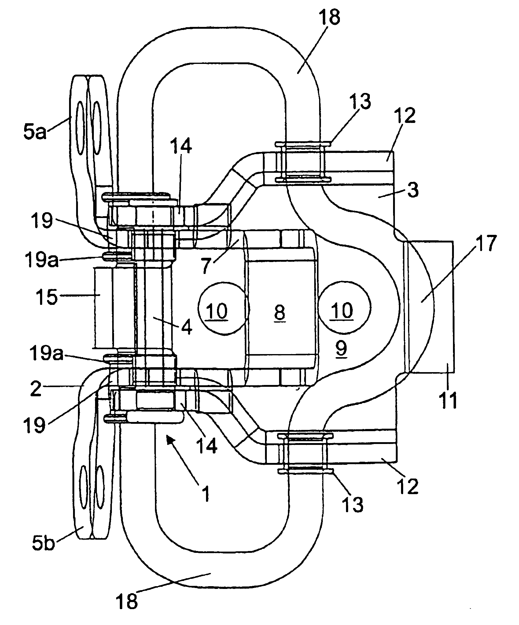
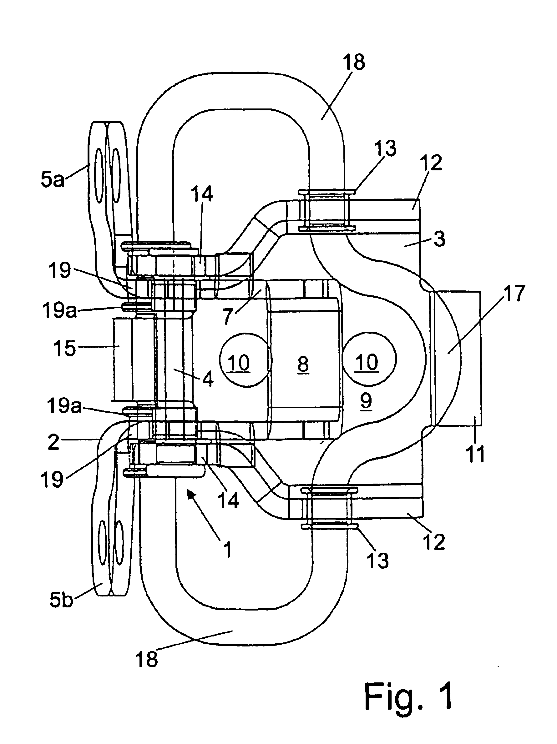
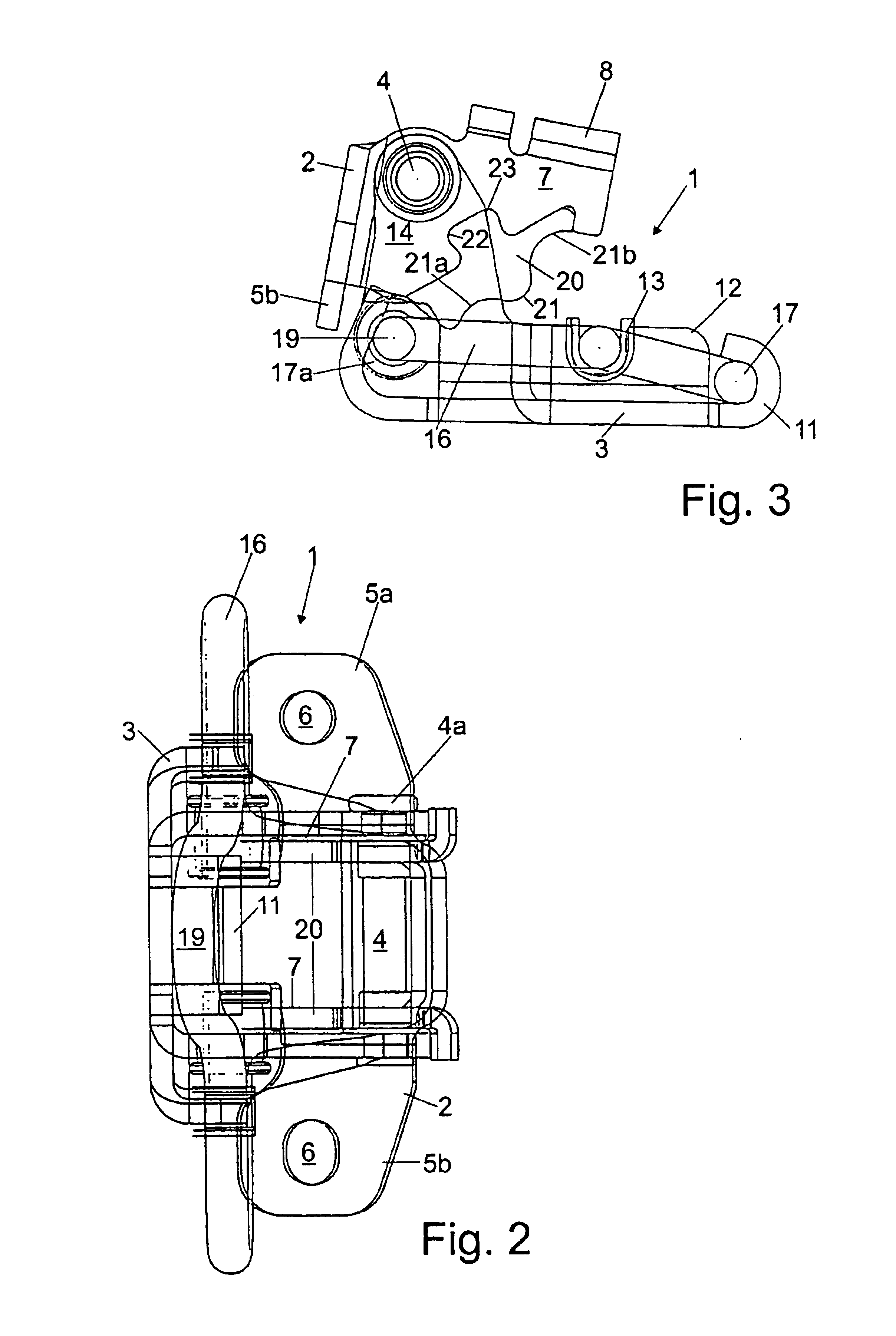
The door hinge 1 shown in FIG. 1 to 3 comprises a first hinge half 2, which is to be fastened to a door pillar of a vehicle body, and a second hinge half 3, which is to be fastened to the door of a vehicle, the first hinge half 2 and the second hinge half 3 being connected to each other via a hinge pin 4 which is held fixedly on the second hinge half 3 and rotatably on the first hinge half 2 with a running fit in the respectively assigned end joints. It can be seen that the two hinge halves 2, 3 in each case have two end joints designed for the pinning together, the hinge pin 4 being designed with a head 4a which forms a stop at one end and at its other end is secured in a known manner by riveting.

The first hinge half 2 has fastening tabs 5a, 5b which are directed outward on both sides, in each case have a hole 6 passing through them and are intended for the fastening of the hinge half 2 to the door pillar of a motor vehicle body. The end-joint region in each case with a gudgeon of ...


PUM


Abstract

The invention relates to a door hinge for a door of a vehicle. The inventive hinge comprises a first and a second guiding arrangement (7, 20; 7, 30, 31) for fixing at least one holding position for the door hinge. Said hinge also comprises a first and a seond free end (19) which engage with the first and second guiding arrangements. Said ends belong to a spring element (16). The aim of the invention is to provide a door hinge that is constructed in a compact manner and reliably enables to fix the door hinge, whereby moments crosswise in relation to the swivelling axis are prevented. To this end, the first free end (19) and the second free end (19) respectively are arranged in a mirror-inverted manner in relation to each other and at the remaining halve (3) of the hinge.

Description

BACKGROUND OF THE INVENTIONThe invention relates to a door hinge for a vehicle door, comprising a first and a second hinge half, each of which can alternatively be fastened to one of the door assembly parts door and door pillar; a hinge pin which connects the first and the second hinge halves pivotably to each other; a first guiding arrangement which is formed on one of the first and second hinge halves and is intended for securing at least one holding position for the door hinge; a first free end of a spring element secured on the other of the first and second hinge halves, which free end interacts with the first guiding arrangement; a second guiding arrangement which is formed on the one hinge half and is intended for securing at least one holding position for the door hinge; and a second free end of a spring element secured on the other hinge half, which end interacts with the second guiding arrangement.DE-A-32 23 938 describes a door-securing means which is combined with a hinge...

Claims


Application Information

Patent Timeline
IPC IPC(8): E05D11/00E05D11/10B60J5/04
CPCE05D11/1042Y10T16/5389Y10T16/54029E05Y2900/531
Inventor NIKOLIC, ZELJKODELL, GEORGMORAWETZ, RICHARD
Owner EDSCHA AG
Learn More