Vehicle occupant position and velocity sensor

a technology of vehicle occupant position and velocity sensor, which is applied in the direction of child seats, instruments, tractors, etc., can solve the problems of/will be injured, etc., and achieve the effect of accurate discrimination

Inactive Publication Date: 2002-06-11
AUTOMOTIVE TECH INT
View PDF20 Cites 9 Cited by
  • Summary
  • Abstract
  • Description
  • Claims
  • Application Information

AI Technical Summary

Benefits of technology

In yet another preferred implementation, a beam of radiation is moved back and forth across the occupant illuminating various portions of the occupant and with appropriate algorithms the position of the occupant in the seat is accurately determined.
It is a principal object of this invention to provide an occupant position sensor which reliably permits, and in a timely manner, a determination to be made that he / she is out of position, or will become out of position, and likely to be injured by a deploying airbag.
It is also a principal object of this invention to provide a system which will accurately discriminate between the occupant's head or chest and other parts of the body in determining the occupant's position and velocity.
It is another object of this invention to independently prevent the deployment of the driver or passenger airbags if either occupant is out of position.

Problems solved by technology

When the vehicle is subjected to a crash of sufficient magnitude as to require deployment of the passive protective device, and the sensor system has determined that the device is to be deployed, the occupant position sensor and associated electronic circuitry determines the position of the vehicle occupant relative to the airbag and disables deployment of the airbag if the occupant is positioned so that he / she is likely to be injured by the deploying airbag.

Method used


Image

  • Vehicle occupant position and velocity sensor
  • Vehicle occupant position and velocity sensor
  • Vehicle occupant position and velocity sensor

Examples


Embodiment Construction

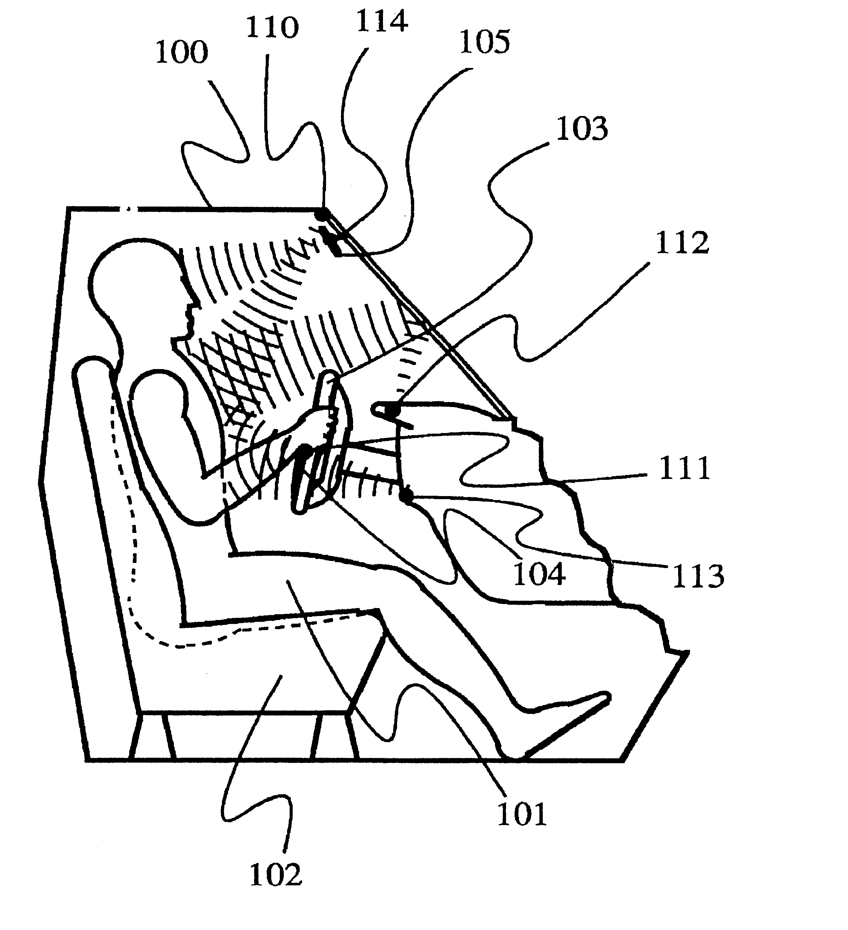
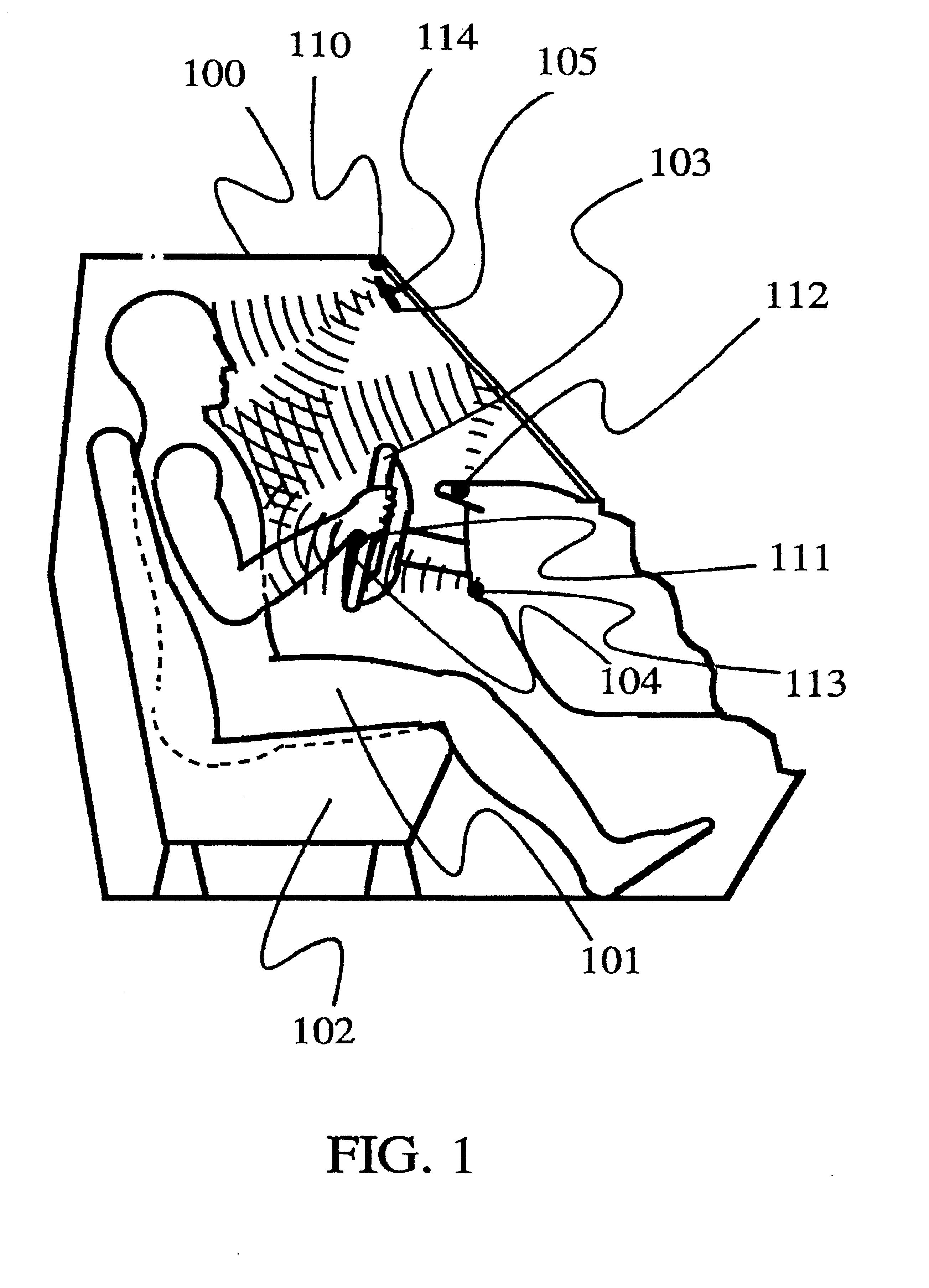
Referring now to the drawings, a section of the passenger compartment of an automobile is shown generally as 100 in FIG. 1. A driver of a vehicle 101 sits on a seat 102 behind a steering wheel 103 which contains an airbag assembly 104. Five transmitter and / or receiver assemblies 110, 111, 112, 113 and 114 are positioned at various places in the passenger compartment to determine the location of the head, chest and torso of the driver relative to the airbag. Usually, in any given implementation, only one or two of the transmitters and receivers would be used depending on their mounting locations as described below.

FIG. 1 illustrates several of the possible locations of such devices. For example, transmitter and receiver 110 emits ultrasonic acoustical waves which bounce off the chest of the driver and return. Periodically a burst of ultrasonic waves at about 50 kilohertz is emitted by the transmitter / receiver and then the echo, or reflected signal, is detected by the same or differen...


PUM


Abstract

An occupant position sensor utilizing either ultrasonic, microwave or optical technologies, or seatbelt spool out and seat position sensors, are used as inputs to the primary vehicle crash sensor circuit to permit the longest possible sensing time before the occupant gets proximate to the airbag and is in danger of being injured by the deploying airbag. The sensor further disables the inflatable restraint system if the occupant is in danger of being injured by the system deployment. Separate systems are used for the driver and passenger to permit the optimum decision to be made for each occupant.

Description

BACKGROUND OF THE INVENTIONCrash sensors for determining that a vehicle is in a crash of sufficient magnitude as to require the deployment of an inflatable restraint system, or airbag, are either mounted in a portion of the front of the vehicle which as crushed by the time that sensor triggering is required, the crush zone, or elsewhere such as the passenger compartment, the non-crush zone. Regardless of where sensors are mounted there will always be crashes where the sensor triggers late and the occupant has moved to a position near to the airbag deployment cover. In such cases, the occupant may be seriously injured or even killed by the deployment of the airbag. This invention is largely concerned with preventing such injuries and deaths by preventing late airbag deployments.In a Society of Automotive Engineers (SAE) paper by Mertz, Driscoll, Lenox, Nyquist and Weber titled "Response of Animals Exposed to Deployment of Various Passenger Inflatable Restraint System Concepts for a V...

Claims


Application Information

Patent Timeline
Patent Type & Authority Patents(United States)
IPC IPC(8): B60N2/00B60N2/26B60N2/02B60R22/18B60N2/48B60R21/01B60R22/20B60N2/28B60R16/02B60R1/08G01S17/88G01S15/88G01S15/00G01S15/87G01S7/02G01S17/00G01S7/48G01S7/41G01S7/539G06K9/00B60R22/00B60R21/26B60R22/48B60R21/20B60R1/12G01S13/00G01S15/06G01S13/04G01S17/89B60R16/037B60R21/0132B60R21/0134B60R21/015B60R21/2165B60R21/276
CPCB60N2/002B60N2/0248B60N2/0276B60R1/088B60R16/037B60R22/20B60R25/25G01S7/417G01S7/4802G01S7/539G01S15/87G01S15/88G01S17/88G06K9/00362B60R21/01554B60R21/01536B60R21/01516B60R21/01534B60R21/01538B60R21/01542B60R21/01552B60N2/0232B60R21/01544B60N2002/0268B60R21/0132B60R21/0134B60R21/21656B60R21/276B60R2001/1223B60R2021/0027B60R2021/26094B60R2021/2765B60R2022/4825G01S13/04G01S15/06G01S17/89B60N2002/0272B60R21/01548G06V40/10B60N2/0272B60N2/0268B60N2/02246
Inventor BREED, DAVID S.CASTELLI, VITTORIODUVALL, WILBUR E.JOHNSON, WENDELL C.PATEL, RASHIK MANGUBHAI
Owner AUTOMOTIVE TECH INT
Why Eureka
Try Eureka