Normally open reverse flow flapper valve

Inactive Publication Date: 2005-02-08
PRATT & WHITNEY CANADA CORP
View PDF16 Cites 37 Cited by
  • Summary
  • Abstract
  • Description
  • Claims
  • Application Information

AI Technical Summary

Benefits of technology

One object of the present invention is to provide a fluid flow actuated valve for controlling th

Problems solved by technology

The resulting oversupply of cooling air increases the Specific Fuel Consumption (SFC) of the gas turbine engine.
Both Fugii's and Smirra's valves are complicated and include more moving parts than the two flap members, which compromises the reliability of their

Method used


Image

  • Normally open reverse flow flapper valve
  • Normally open reverse flow flapper valve
  • Normally open reverse flow flapper valve

Examples


Embodiment Construction

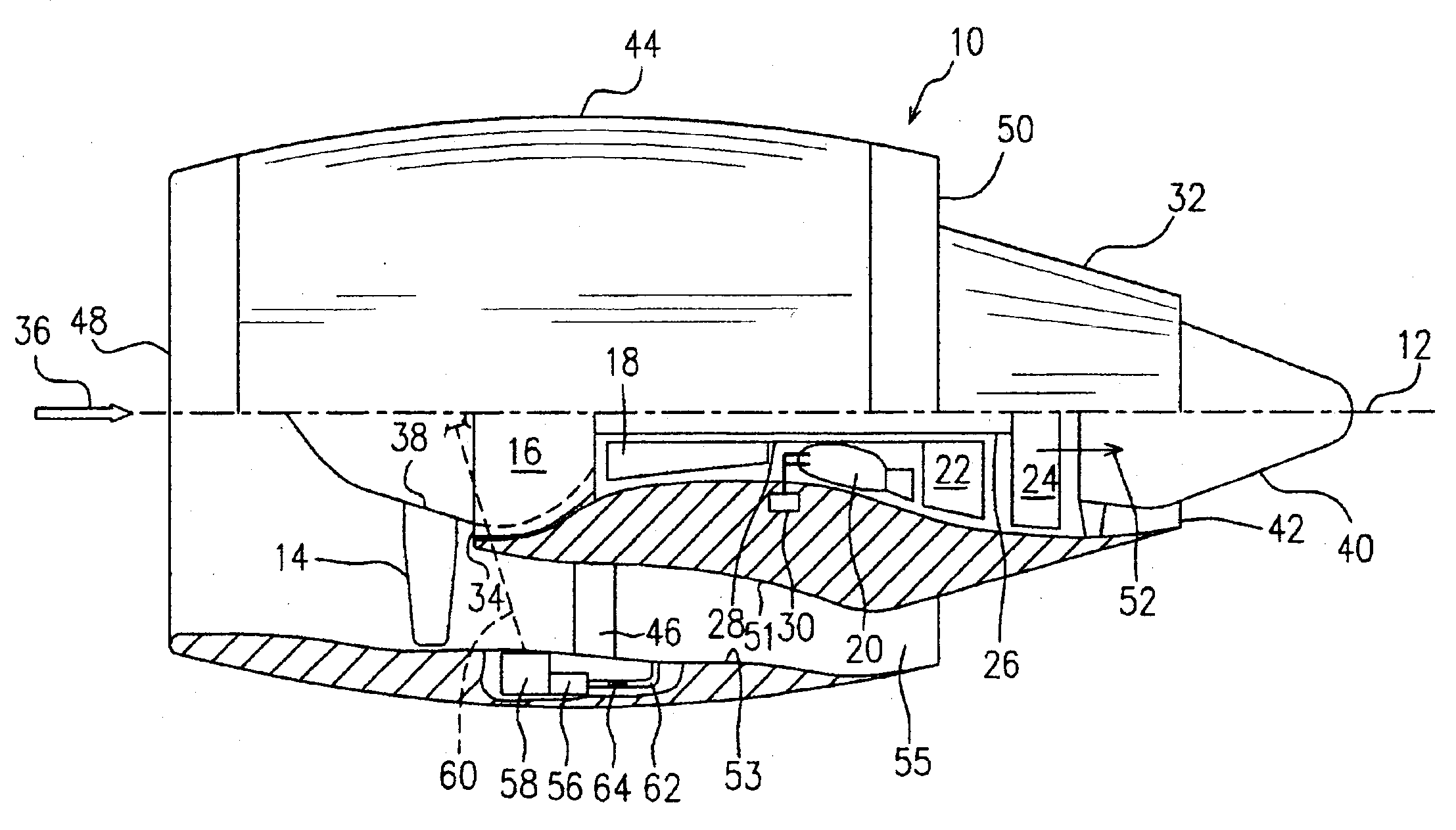
Referring to the drawings, particularly FIG. 1, an exemplary aircraft gas turbine engine 10 includes in serial flow communication about a longitudinal centerline axis 12, a fan having a plurality of circumferentially spaced apart fan blades 14, a low pressure compressor 16, a high pressure compressor 18, an annular combustor 20, a high pressure turbine 22 and a low pressure turbine 24. The low pressure turbine 24 is securely connected to both the low pressure compressor 16 and the fan blades 14 by a first rotor shaft 26, and the high pressure turbine 22 is securely connected to the high pressure compressor 18 by a second rotor shaft 28. Fuel injecting means 30 are provided for selectively injecting fuel into the combustor 20 for powering the engine 10.

An annular casing 32 surrounds the engine 10 from the low pressure compressor 16 to the low pressure turbine 24 and defines, with the low pressure compressor 16, a low pressure compressor inlet 34 for receiving a portion of ambient air...


PUM


Abstract

A fluid flow actuated valve for controlling the fluid flow in a conduit comprises a support structure adapted to be mounted within the conduit and at least one flap member pivotally mounted to the support structure. The at least one flap member is pivotable between an first position for a minimum fluid flow and a second position for a maximum fluid flow. A torsion spring is attached to the at least one flap member to urge the same to pivot against a fluid pressure differential, from the first position to the second position when the fluid pressure differential is smaller than a predetermined level.

Description

FIELD OF THE INVENTIONThe field of the invention is in the area of valves for controlling the fluid flow in a conduit, and particularly relates to a flow actuated valve for controlling fluid flow in a conduit of cooling systems of aircraft gas turbine engines.BACKGROUND OF THE INVENTIONElectrical and mechanical equipment often requires cooling while in operation. Both liquid (e.g. oil) and gas (e.g. air) cooling schemes are well known. Air cooling schemes may be either active (e.g. fan driven) or passive (i.e. rely on an existing pressure gradient to introduce a flow of cooling air to the equipment). In gas turbine engine applications employing a passive air cooling scheme to cool the on-board generator(s), a minimum amount of airflow is required to cool the generator. A pipe that is attached to the bypass duct on the gas turbine engine has been sized to allow this minimum mass flow of air when the air pressure difference between the bypass duct and the atmosphere is very small, for...

Claims


Application Information

Patent Timeline
IPC IPC(8): F01D25/12F01D25/08F02C7/16F02C7/32F02C7/00F16K17/20F16K17/30F02C7/18F16K15/03F16K15/02F24F13/14F24F11/75
CPCF01D25/12F02C7/18F02C7/32F16K15/038F16K17/30F16K15/035Y02T50/675F24F2013/146Y10T137/787Y10T137/7875Y02T50/60F16K15/033
Inventor AITCHISON, PAUL ARCHIBALDGERMAIN, PATRICK DAVIDSMITH, HENRY
Owner PRATT & WHITNEY CANADA CORP
Why Eureka
Try Eureka