Smart accelerator pedal

a technology of accelerator pedal and control device, which is applied in the direction of mechanical control device, controlling member, limiting/preventing/returning movement of parts, etc., can solve the problem of too elaborate design of accelerator pedal with controllable hydraulic cylinder, insufficient uniform rise of required force to alert the motorist of a dangerous situation, and difficult actuation of the gas pedal elemen

Inactive Publication Date: 2005-02-08
ELEKTRONIK
View PDF3 Cites 8 Cited by
  • Summary
  • Abstract
  • Description
  • Claims
  • Application Information

AI Technical Summary

Benefits of technology

The pedal element may comprise a pedal lever element and an accelerator pedal element. The pedal lever element may be connected to the floor plate and moveable about the center of rotation of the gas pedal. The accelerator pedal element can be connected to the pedal lever element, and moveable about the center of rotation of the accelerator pedal. This allows for a comfortable operation.
The advantages achieved with the invention consist especially in the suddenness with which, the motor unit places a counterforce against the foot actuation force of the motorist. In this manner, the motorist is alerted to a dangerous situation and is able to react appropriately. If the motor unit is again switched off, the counterforce is, just as suddenly, no longer present. In this manner, the motorist is alerted of the fact that the dangerous situation is rectified. In addition, the design is less elaborate and more effective than prior designs.

Problems solved by technology

Though use of the valve makes actuation of the gas pedal element more difficult by reducing the flow rate of the hydraulic oil, the uniform rise of the required exertion of force is not sufficient to alert the motorist of a dangerous situation.
In addition, the design of the accelerator pedal with the controllable hydraulic cylinder is too elaborate.

Method used


Image

  • Smart accelerator pedal
  • Smart accelerator pedal
  • Smart accelerator pedal

Examples


Embodiment Construction

The preferred embodiments of the present invention will now be described with reference to FIGS. 1-5 of the drawings. Identical elements in the various figures are designated with the same reference numerals.

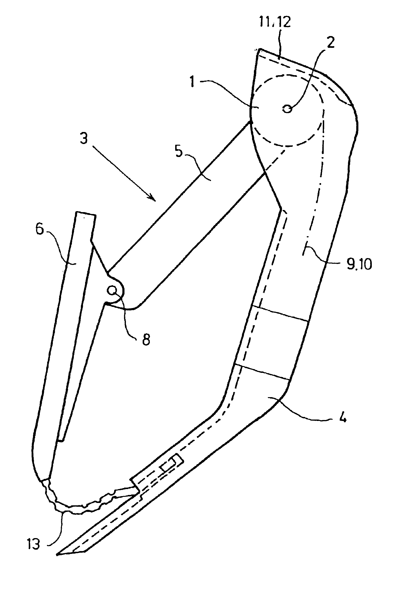
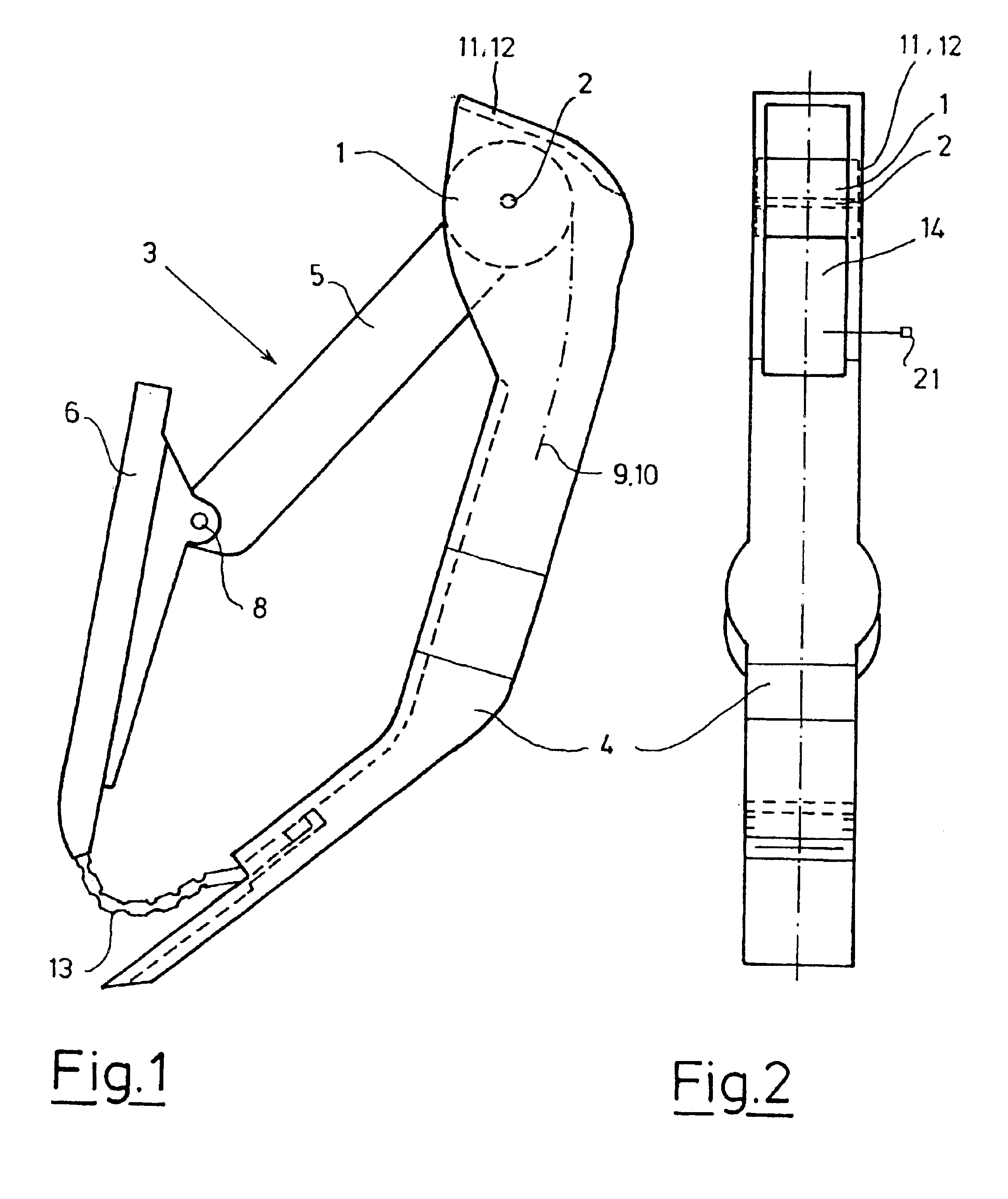
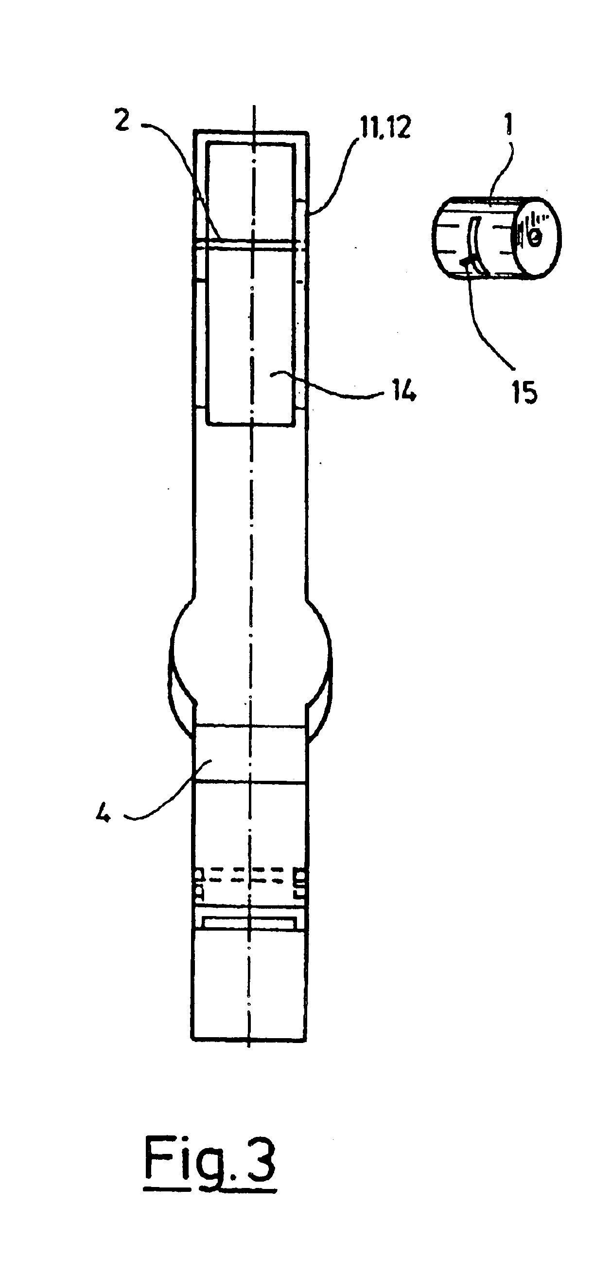
FIGS. 1 to 3 show a smart accelerator pedal. It consists of a pedal lever element 5, rotatably attached, at the center of rotation of the gas pedal 2, to the floor plate 4. An accelerator pedal element 6 is rotatably attached to the pedal lever element at a center of rotation of an accelerator pedal 8. The other end of the accelerator pedal element 6 is connected to the base unit 4 via a link coupling element 13. This ensures that the accelerator pedal element 6 is always positioned properly in relation to the foot of the motorist. The pedal lever element 5, and thus the accelerator pedal element 6, is always returned to its initial position with the help of two retraction elements 11, 12.

Two damper elements 9, 10 provide the damping of the actuation of the pedal lever element u...


PUM


Abstract

An accelerator pedal device includes at least one pedal element that can be moved about the center of rotation of a gas pedal, opposite a base element, and which has at least one retraction element, and at least one damper element to dampen the pedal actuation movement and the pedal retraction movement of the pedal element. A control unit is provided, connected to a sensor element, which controls the motor unit as follows:
    • a) sensing, through the control sensor element, a condition that deviates from the prescribed normal condition;
    • b) switching on the motor unit that generates a motor counterforce that acts upon the pedal element in addition to the damping force of the damper element; and
    • c) switching off the motor unit when the prescribed normal condition is sensed by the control sensor element.

Description

FIELD OF THE INVENTIONThe invention relates to an accelerator pedal control device that includes a control unit connected to a sensor element, for controlling the accelerator pedal in relation to a prescribed normal condition.BACKGROUND OF THE INVENTIONAccelerator pedal control devices having a damper element used to dampen the pedal actuation movement and the pedal retraction movement of the pedal element, and a control unit connected to a sensor element, to further dampen the pedal actuator movement under specific conditions, are known. A device of this type mentioned above is known from DE 298 05 253 U1. There, the pedal is connected to a piston rod of a piston of a hydraulic cylinder. Its cylinder element is filled with a hydraulic liquid. A hydraulic line is connected to the cylinder element beyond the highest and lowest position of the piston. A hydraulic valve, which is controlled by a decision logic, is located in the hydraulic line. The decision logic is designed as a progr...

Claims


Application Information

Patent Timeline
Patent Type & Authority Patents(United States)
IPC IPC(8): B60K26/02B60K26/00F02D11/02F02D11/00G05G1/30G05G5/03
CPCB60K26/021F02D11/02G05G5/03G05G1/30Y10T74/20534Y10T74/2054
Inventor APEL, PETERWILCZEK, KLAUS
Owner ELEKTRONIK
Why Eureka
Try Eureka