
Access control for electronic blasting machines

a technology of electronic blasting machine and access control, which is applied in the direction of electric fuzes, ammunition fuzes, lighting and heating apparatus, etc., can solve the problems of inability to provide absolute safety and security of blasting system, and the possibility of inappropriate detonator actuation, so as to improve safety and security

Inactive Publication Date: 2005-02-08
ORICA EXPLOSIVES TECH PTY LTD
View PDF20 Cites 31 Cited by
  • Summary
  • Abstract
  • Description
  • Claims
  • Application Information

AI Technical Summary

Benefits of technology

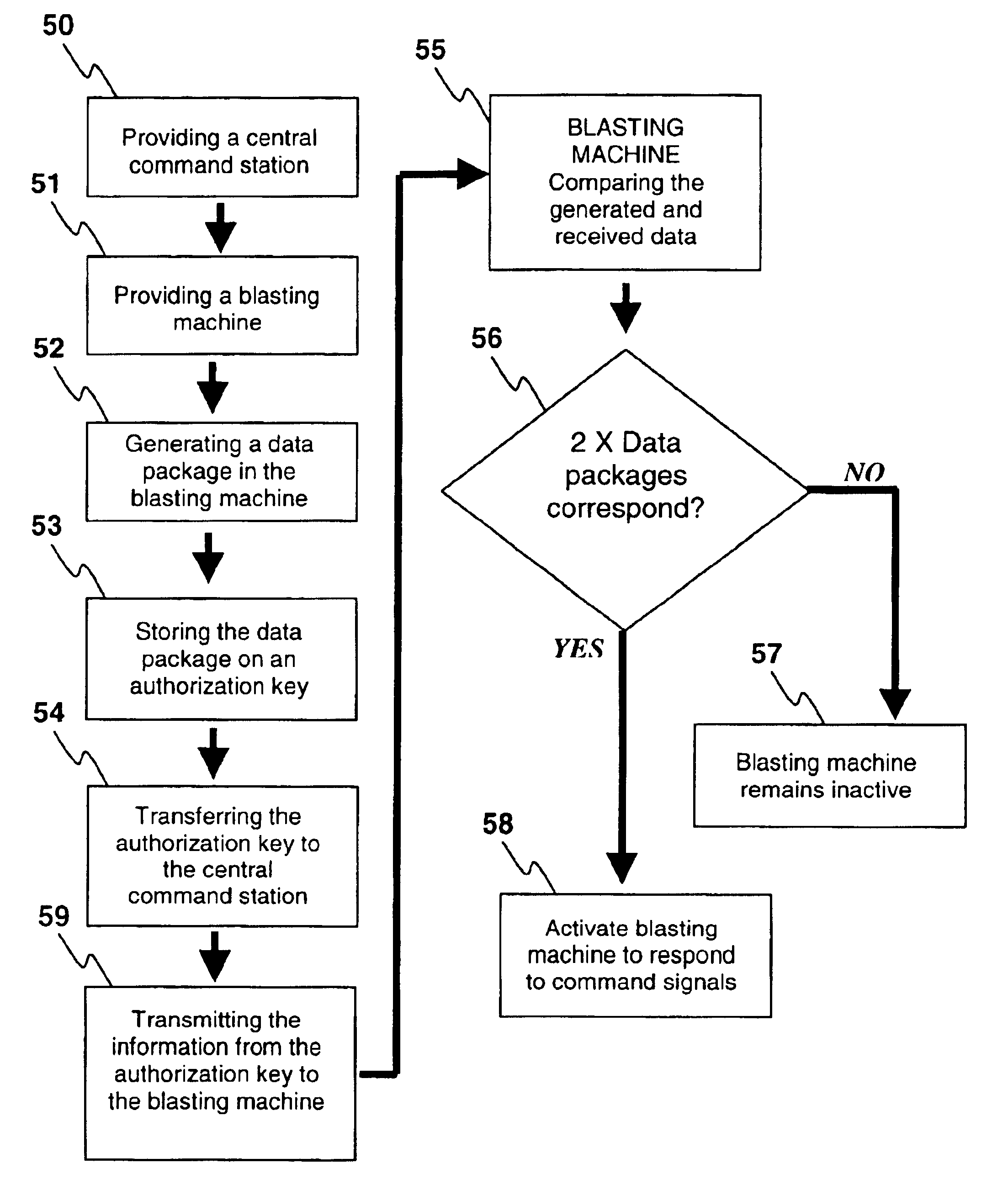
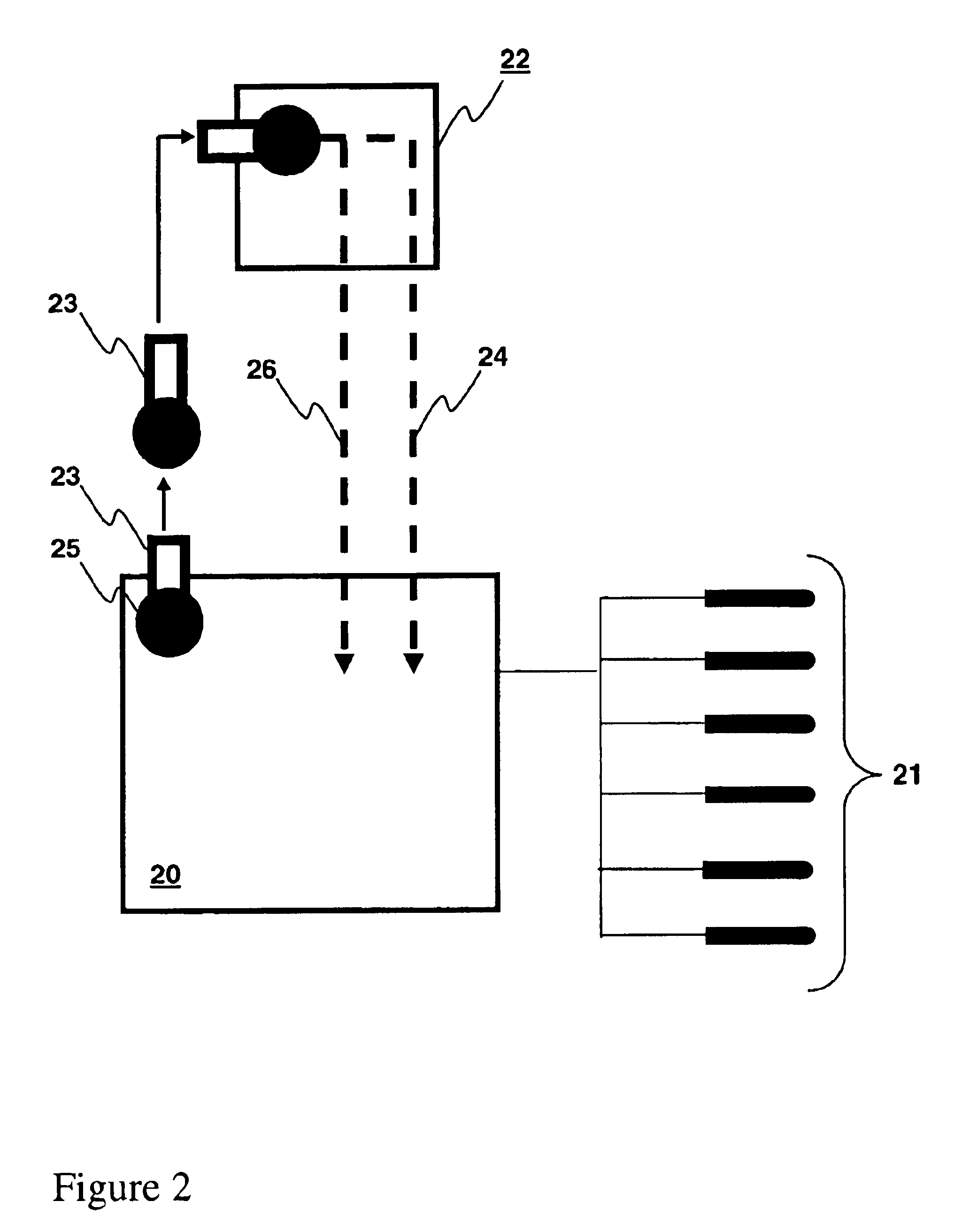
"The present invention provides an improved system for controlling detonators in a safe and secure manner. The system involves a central command station and a group of detonators in signal communication with each other. The central command station transmits command signals and receives data packages from the detonators. The data packages contain a randomly generated access code specific to each detonator. The central command station verifies the data packages with the command signals and the access code before transmitting the data packages to the detonators. The system also includes encryption means and decryption means for the command signals and data packages. The invention also provides a method for controlling detonators using the system. The technical effects of the invention include improved safety and security in the detonation process and better verification of the detonators' identity."

Problems solved by technology

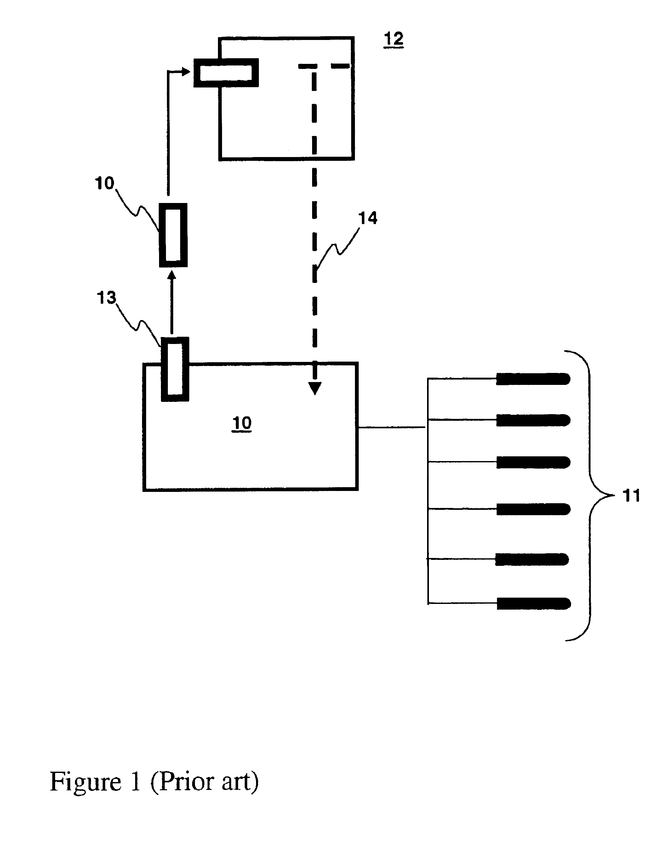
Nonetheless, no blasting system can provide absolute safety and security, and there remains a need for improved blasting systems configured to reduce the possibility of inappropriate detonator actuation or unauthorized use.

Method used


Image

  • Access control for electronic blasting machines
  • Access control for electronic blasting machines
  • Access control for electronic blasting machines

Examples


example 1

Adaptation of the I-Kontm Blasting System

The i-kon blasting system (Orica Limited) provides millisecond controlled initiation timing. The field trials of the system and methods of the present invention involved adaptation of the i-kon system, at least in part, by the integration of the Central Blasting System™ (CBS). The i-kon CBS was tested using various methods in various stages including:Establishment of proper equipment functioning by remote control (air-to-air testing)Establishment of contact between a central command station and a blasting machine through normal network establishment via a leaky feederTesting of signal strengths between the system componentsConducting ‘dummy’ firings of the i-kon CBS system

The above-mentioned tests were used to refine the system, and make desirable improvements. The tests determined that modifications were required to antennae, leaky feeder lines, leaky feeder amplifiers, and radio modems to establish proper communication between system compon...

example 2

Functional Testing of the Adapted I-Kon Cbs Blasting System

Functional field testing was conducted using a total of 26 live and 304 dummy detonators, arranged into several ‘Loggers’. All 330 detonators were programmed and fired over the full system specifications (260 Ohm harness wire per logger, and 130 Ohm for the firing cables).

The following preparations were used at the blast site:

Logger#1: 22 dummy detonatorsLogger#2: 25 dummy detonatorsLogger#3: 15 dummy detonatorsLogger#4: 18 dummy detonatorsLogger#5: 25 dunmmy detonatorsLogger#6: 14 live detonators with 0, 2000, 4000, 6000, 4×8000, 12000, 5×15000 ms delaysLogger#7: 11 live detonators with 0, 2000, 4000, 6000, 4×8000, 12000, 2×15000 ms delaysLogger#8: 200 dummy detonators

After the circuits were tested for their integrity, the i-kon blasting machine was connected to the Loggers in parallel via the blasting cable.

Next, the authorization key was ‘initialized’ by inducing the blasting machine to transfer the serial number of the b...


PUM


Abstract

Blasting apparatuses and methods control actuation of a plurality of detonators, and involve the use of one or more authorization keys each associated with a blasting machine. The authorization key(s) are transferable from the blasting machine(s) to a central command station, each authorization key storing a data package comprising a randomly generated access code generated by its corresponding blasting machine. Transfer of the one or more authorization keys to a central command station allows the data packages (and associated randomly generated access codes) to be transmitted by the central command station for receipt by the blasting machine(s).

Description

FIELD OF THE INVENTIONThe present invention relates to the field of remote actuation of detonators. More specifically, the invention relates to systems and methods for improving the safety and / or preventing unauthorized usage of blasting systems involving detonators.BACKGROUND TO THE INVENTIONTypical blasting systems can involve one or more blasting machines, each in direct communication with a plurality of detonators. Command signals can be transmitted to the blasting machine(s) by a central command station that is located remote from the vicinity of the blast. Such command signals may include signals to ARM, FIRE or DISARM the detonators.The communication between the central command station and the blasting machine typically occurs via radio-communication, but may also involve direct electric or non-electric connection. Likewise, the communication between the blasting machine and the detonators may also involve radiocommunication, but more typically involves direct connection, for...

Claims


Application Information

Patent Timeline
Patent Type & Authority Patents(United States)
IPC IPC(8): F42D1/00F42D1/045F42D1/05F42C15/42F42D5/00
CPCF42C15/42F42D5/00F42D1/05F42D1/045
Inventor HUMMEL, DIRKCRAMER, OLAF
Owner ORICA EXPLOSIVES TECH PTY LTD
Learn More