Cutting tool insert and cutting tool

Active Publication Date: 2005-02-08
DAISHOWA SEIKI CO LTD
View PDF17 Cites 11 Cited by
  • Summary
  • Abstract
  • Description
  • Claims
  • Application Information

AI Technical Summary

Benefits of technology

The present invention aims to solve the above-mentioned conventional problems. It is the object of this invention to provide a cutting tool insert capable of forming a cylindrical envelope, realizing a suff

Problems solved by technology

However, with the cutting tool on which the polygonal insert is mounted, it has been difficult to realize a large axial rake angle.
However, if the axial rake angle is set to this large value so as to realize smooth cutting into a work piece at the time of cutting operations, to allow sufficient improvement in cuttin

Method used


Image

  • Cutting tool insert and cutting tool
  • Cutting tool insert and cutting tool
  • Cutting tool insert and cutting tool

Examples


Example

Embodiment 1

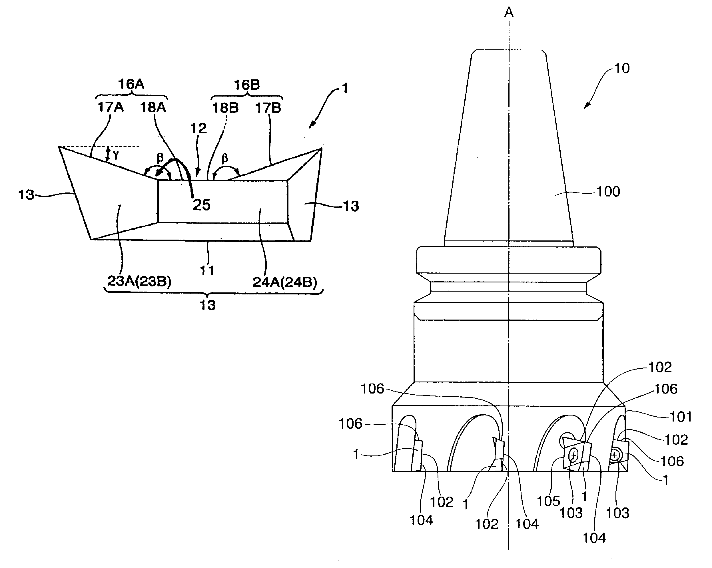
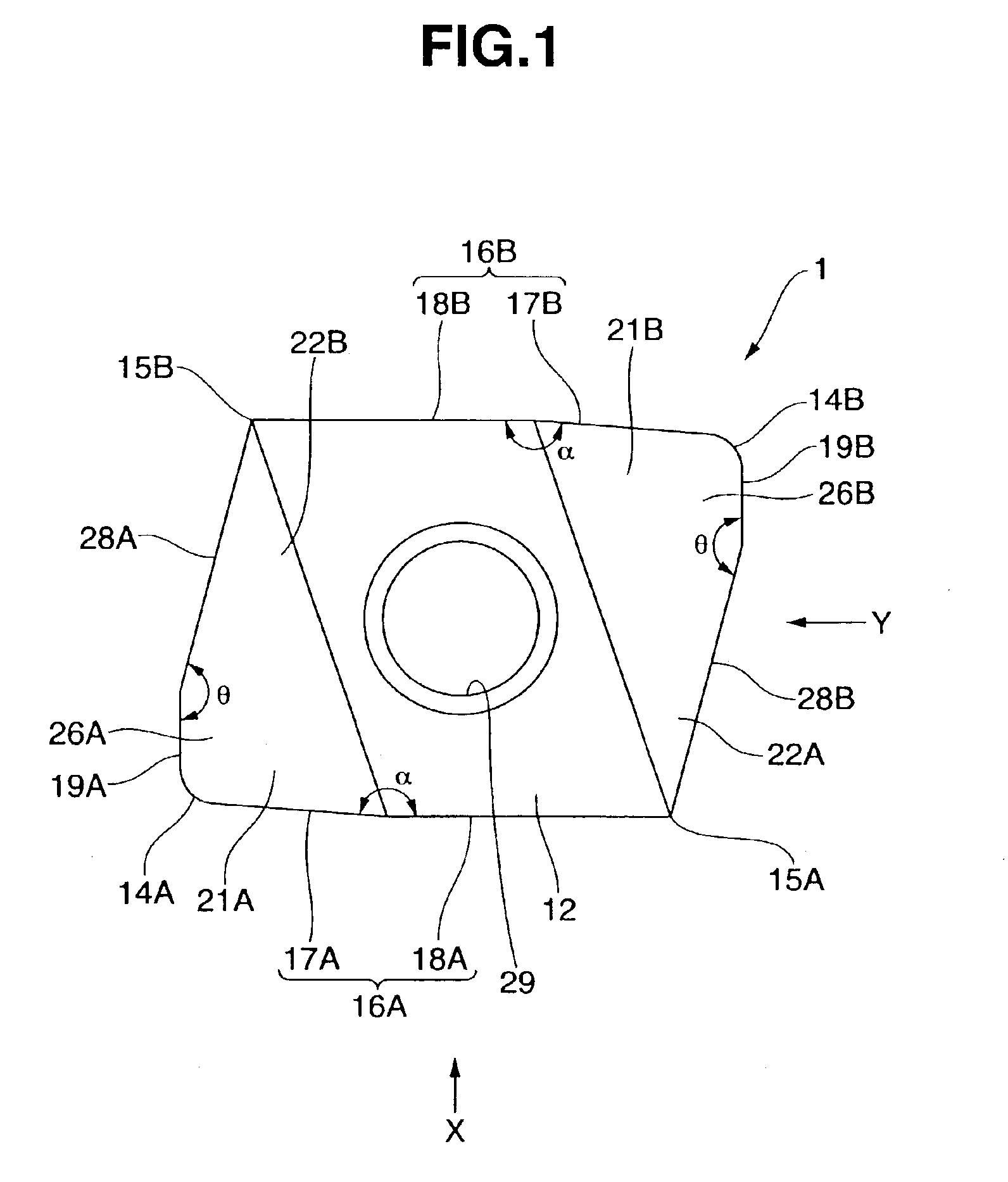
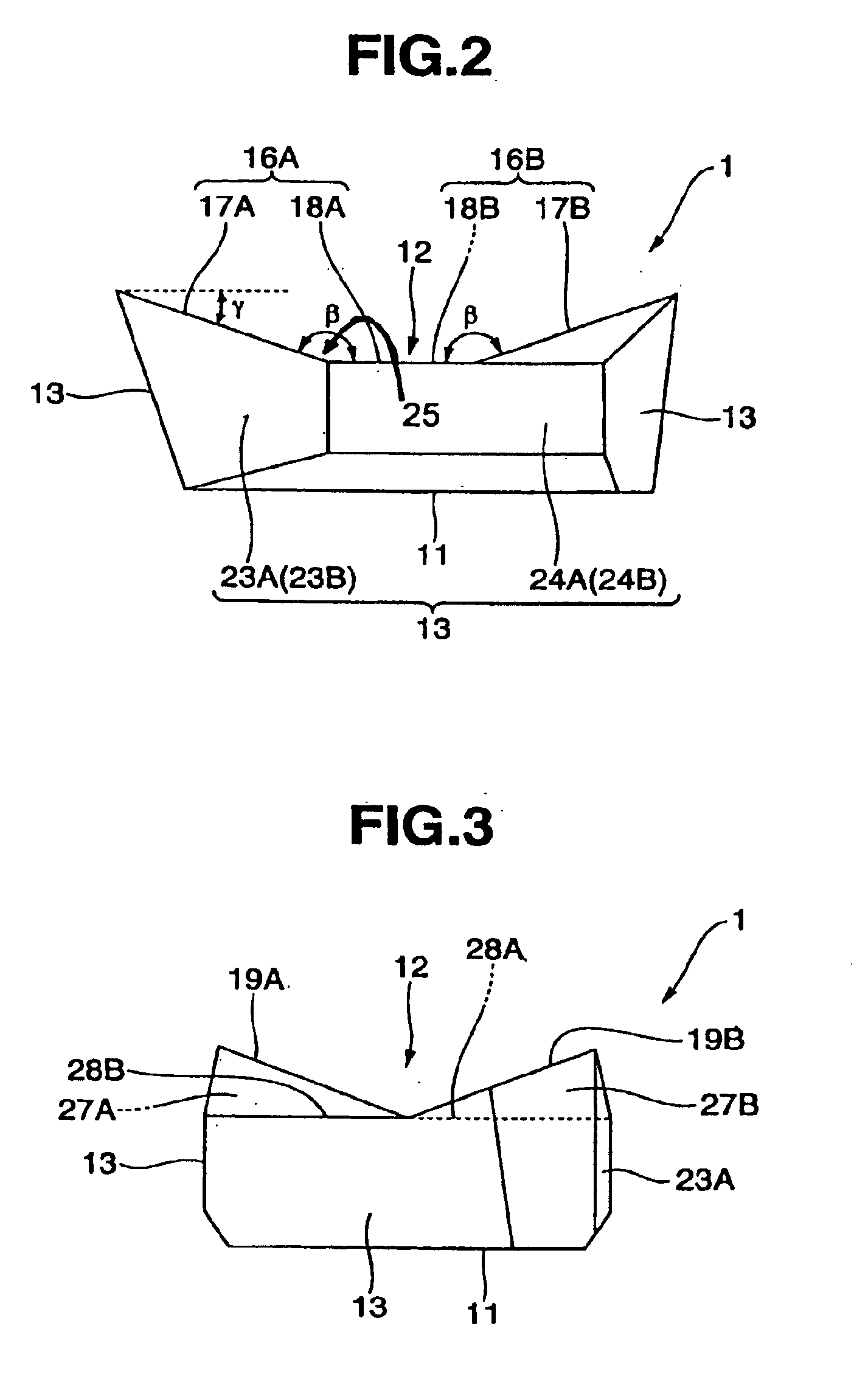
FIG. 1 is a top view of a cutting tool insert according to Embodiment 1 of this invention. FIG. 2 is a side view of the insert of FIG. 1 as seen from the direction indicated by arrow X. FIG. 3 is a side view of the insert of FIG. 1 as seen from the direction indicated by arrow Y. FIG. 4 is a side view of a cutting tool on which the cutting tool inserts are mounted according to Embodiment 1 of this invention. FIG. 5 is a bottom view of the cutting tool shown in FIG. 4. FIG. 6 is an enlarged view of a part of the cutting tool shown in FIG. 4. FIG. 7 is an enlarged view of a part of the cutting tool shown in FIG. 5.

As shown in FIGS. 1 to 7, a cutting tool insert 1 according to Embodiment 1 is in a substantially plate form and of substantially parallelogrammic (polygonal) shape as viewed from above. The insert 1 includes a seat face (or bottom face) 11, a top face 12 opposite the seat face 11, and side faces 13 extending from the seat face 11 towards the top face 12. The edg...

Example

Embodiment 2

Explanations are hereinafter given about the cutting tool insert and the cutting tool on which this insert is mounted according to Embodiment 2 of this invention, with reference to the attached drawings.

FIG. 8 is a top view of a cutting tool insert according to Embodiment 2 of this invention. FIG. 9 is a side view of the insert shown in FIG. 8. FIGS. 10 and 11 are side views of a part of the cutting tool on which the cutting tool insert is mounted according to Embodiment 2 of this invention.

Concerning Embodiment 2, members similar to those described in Embodiment 1 are given the same reference numerals as in Embodiment 1, and any detailed description thereof is omitted.

The main difference between an insert 2 of Embodiment 2 and the insert 1 of Embodiment 1 is that the insert 2 is in a substantially triangular shape as viewed from above. Specifically, as shown in FIGS. 8 through 11, the insert 2 is a substantially plate form of substantially triangular (polygonal) shape a...


PUM

PropertyMeasurementUnit
Angleaaaaaaaaaa
Currentaaaaaaaaaa
Currentaaaaaaaaaa

Abstract

The cutting tool insert 1 is in a substantially plate form and of polygonal shape and is provided with a major cutting edge 16A (or 16B) extending from one corner 14A (or 14B) toward the other corner 15A (or 15B). The major cutting edge 16A (or 16B) comprises a first edge line and a second edge line that meet to form an obtuse angle, which causes the area where the first and second edge lines meet to protrude slightly outwards, as viewed from above. The first edge line slopes down towards the second edge line so that the distance with a seat face 11 decreases gradually as viewed from the side, and the first edge line forms an obtuse angle with the second edge line causing the top face area to dip down towards the seat face. The first edge line is shorter than the second edge line.

Description

BACKGROUND OF THE INVENTION1. Field of the InventionThe present invention relates to an insert mounted on a cutting tool body and also relates to a cutting tool on which this insert is mounted.2. Description of the Related ArtWith a conventional cutting tool that uses an insert mounted on its tool body, a polygonal insert has been employed to make effective use of its corners so that as many positions in one insert as possible can be used. When an insert is mounted on a tool body, the insert is positioned so that it forms a positive axial rake angle, that is, a positive angle relative to the rotation axis of the tool body. Typically, when the axial rake angle becomes large, smooth cutting into a work piece can be realized at the time of cutting operations and the insert is able to execute cutting in more than one position, thereby enabling stable processing with little cutting vibrations. However, with the cutting tool on which the polygonal insert is mounted, it has been difficult ...

Claims


Application Information

Patent Timeline
IPC IPC(8): B23B27/14B23C5/20B23C5/02B23C5/06B23C5/16B23C5/22
CPCB23C5/2221Y10T407/1962Y10T407/23Y10T407/235B23C5/2213
Inventor KUBO, HARUAKI
Owner DAISHOWA SEIKI CO LTD
Why Eureka
Try Eureka